Intel® PXA26x Processor Family Developer’s Manual 4-43
System Integration Unit
4.5 Pulse Width Modulator
Use the Pulse Width Modulator (PWM) to generate as many as two signals to be output from the
processor. The signals are based on the 3.6864-MHz clock and must be a minimum of 2 clock
cycles wide. These signals are output from the processor by configuring the GPIOs.
4.5.1 Pulse Width Modulator Operation
The processor contains two pulse width modulators: PWM0 and PWM1. Each PWM operates
independently of the other, is controlled by its own set of registers. They provide a pulse width
modulated signal on an external pin. Since each PWM contains identical circuitry, a generic
PWMn, where n is 0 or 1, is described.
Each PWM contains:
• Two Pulse Width Modulator channels
• Enhanced Period control through 6-Bit Clock divider and 10-Bit Period counter
• 10-Bit Pulse control
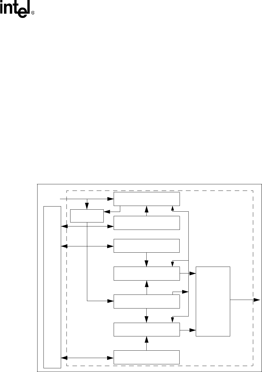
A block diagram of one of the PWMs is shown in Figure 4-3.
Figure 4-3. PWMn Block Diagram
Value of
PWM_DUTYn[DCYCLE]
Comparator
10-bit up counter
Comparator
Value of
PWM_PERVALn[PV]
Value of
PWM_CTRLn[PRESCALE]
6-bit down counter
Clock Gate
PSCLK_PWMn
PWM_OUTn
RESET
SET
FLIP-FLOP
3.6864 MHz
Bus
Interfac
Control Block


