


Intel® PXA26x Processor Family Developer’s Manual 11-13
Fast Infrared Communication Port
each entry is removed, the EIF bit must be checked to determine if any set end or error tag remains
and the procedure is repeated until all set tags are flushed from the FIFO’s bottom entries. When
EIF is cleared, DMA service for the receive FIFO is re-enabled.
Both FIFOs are cleared when the processor is reset. The transmit FIFO is cleared when TXE is 0.
The receive FIFO is cleared when RXE is 0.
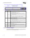
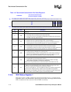
11.3.5 FICP Status Register 0
FICP status register 0 (ICSR0) contains bits that signal the transmit FIFO service request, receive
FIFO service request, receiver abort, transmit FIFO underrun, framing error, and the end/error in
receive FIFO conditions. Each of these hardware-detected events signal an interrupt request to the
interrupt controller.
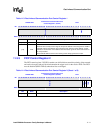
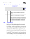
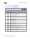
If a bit signals an interrupt request, it signals the interrupt request as long as the bit is set. When the
bit is cleared, the interrupt is cleared. Read/write bits are called status bits. Read-only bits are
called flags. Status bits that must be cleared by software after they are set by hardware are called
sticky status bits. Writing a 1 to a sticky status bit clears it. Writing a 0 to a sticky status bit has no
effect. Read-only flags are set and cleared by hardware. Writes to read-only flags have no effect.
Some bits that cause interrupts have corresponding mask bits in the control registers. These bits are
indicated in the sections that follow.
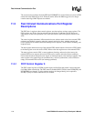
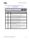
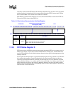
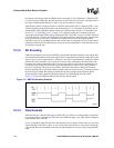
Table 11-5. Fast Infrared Communication Port Data Register
0x4080 000C
Fast Infrared Communication Port
Data Register (ICDR)
FICP
Bit
31 30 29 28 27 26 25 24 23 22 21 20 19 18 17 16 15 14 13 12 11 10 9 8 7 6 5 4 3 2 1 0
Reserved
DATA
Reset 0 0 0 0 0 0 0 0 0 0 0 0 0 0 0 0 0 0 0 0 0 0 0 0 0 0 0 0 0 0 0 0
Bits Name Description
[31:8] — Reserved
[7:0] DATA
TOP/BOTTOM OF TRANSMIT/RECEIVE FIFO:
Read – Read data from front of receive FIFO
Write – Place data at end of transmit FIFO