14-8 Intel® PXA26x Processor Family Developer’s Manual
Inter-Integrated Circuit Sound Controller
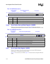
• The Status Register signals the state of the FIFO buffers and the status of the interface that is
selected by the common control register.
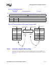
• The Interrupt Registers include the Interrupt Mask Register, the Interrupt Clear Register, and
the Interrupt Test Register.
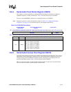
14.6.1 Serial Audio Controller Global Control Register (SACR0)
This register controls common I
2
S functions. All bits are read/write. Table 14-3 shows the bit
layout of SACR0.
The ENB bit controls the I2SLINK, as:
• Clearing ENB to zero does these:
— disables any I2SLINK activity
— resets all receive FIFO pointers and also the counter that controls the I2SLINK
— resets the receive FIFO
— does not affect the transmit FIFO
— the output pin SYNC will not toggle
— de-asserts all DMA requests
— any read accesses to the Data Register (SADR), by the process or, or by the DMA
controller is returned with zeros
— disables all interrupts.
• Setting ENB to one does:
— enables I2SLINK activity
— enables DMA requests.
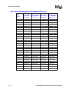
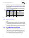
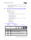
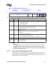
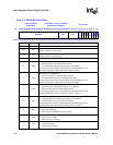
Table 14-3. SACR0 Bit Descriptions (Sheet 1 of 2)
Physical Address
0x4040-0000
Serial Audio Controller Global
Control Register
I
2
S Controller
Bit
31 30 29 28 27 26 25 24 23 22 21 20 19 18 17 16 15 14 13 12 11 10 9 8 7 6 5 4 3 2 1 0
Reserved RFTH TFTH
Reserved
STRF
EFWR
RST
BCKD
Reserved
ENB
Reset 0 0 0 0 0 0 0 0 0 0 0 0 0 0 0 0 0 1 1 1 0 1 1 1 0 0 0 0 0 0 0 0
Bits Name Description
31:16 — Reserved
15:12 RFTH
RECEIVE FIFO INTERRUPT OR DMA THRESHOLD:
Set to value 0 – 15. This value must be set to the threshold value minus 1.
Receive DMA request asserted whenever the receive FIFO has >= (RFTH+1) entries.
11:8 TFTH
TRANSMIT FIFO INTERRUPT OR DMA THRESHOLD:
Set to value 0 – 15. This value must be set to the threshold value minus 1.
Transmit DMA request asserted whenever the transmit FIFO has < (TFTH+1) entries.


