


Intel® PXA26x Processor Family Developer’s Manual 15-21
MultiMediaCard Controller
15.5 MultiMediaCard Controller Register Descriptions
The MMC controller is controlled by a set of registers that software configures before every
command sequence on the MMC bus.
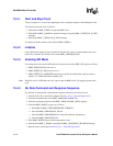
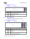
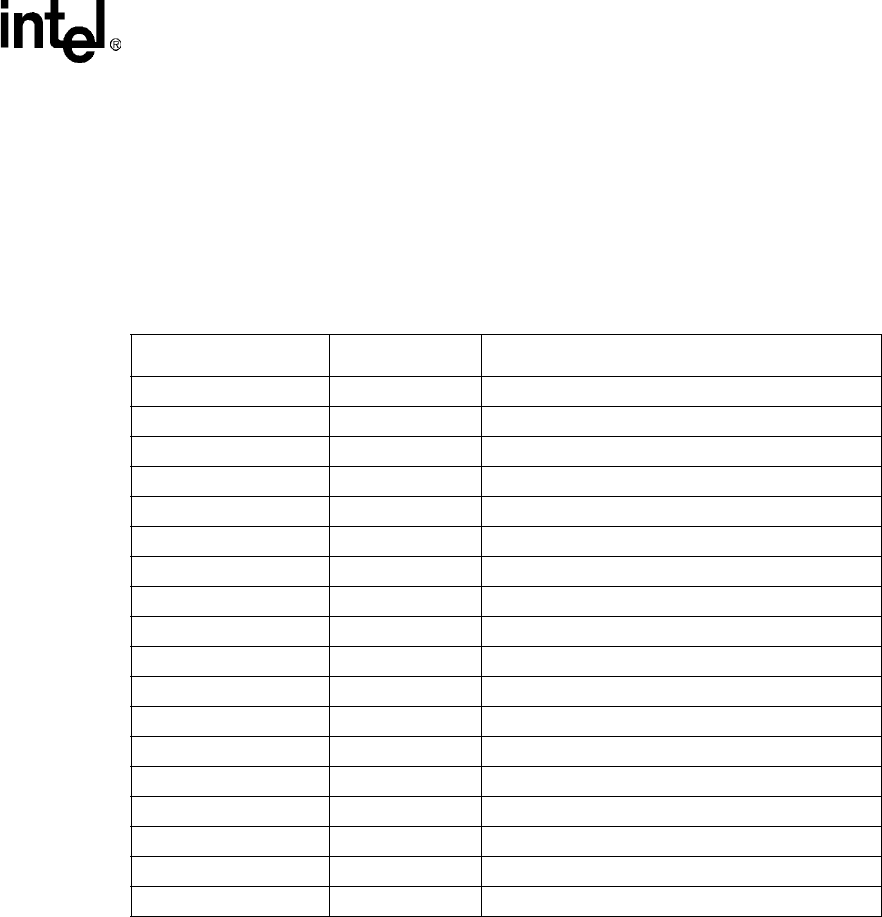
Table 15-6 lists the address, name, and description of the MMC Controller Registers. Table 15-6
through Table 15-24 describe the registers and FIFOs.
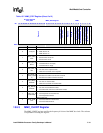
15.5.1 MMC_STRPCL Register
The MMC_STRPCL register allows the software to start and stop the MMC bus clock. This
register is write only and reads are unpredictable. The register bits are described in Table 15-6.
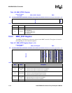
Table 15-5. MMC Controller Registers
Address Name
Description
0x4110 0000 MMC_STRPCL Control to start and stop MMC clock
0x4110 0004 MMC_STAT MMC status register (read only)
0x4110 0008 MMC_CLKRT MMC clock rate
0x4110 000c MMC_SPI SPI mode control bits
0x4110 0010 MMC_CMDAT Command/response/data sequence control
0x4110 0014 MMC_RESTO Expected response time out
0x4110 0018 MMC_RDTO Expected data read time out
0x4110 001c MMC_BLKLEN Block length of data transaction
0x4110 0020 MMC_NOB Number of blocks, for block mode
0x4110 0024 MMC_PRTBUF Partial MMC_TXFIFO FIFO written
0x4110 0028 MMC_I_MASK Interrupt Mask
0x4110 002c MMC_I_REG Interrupt Register (read only)
0x4110 0030 MMC_CMD Index of current command
0x4110 0034 MMC_ARGH MSW part of the current command argument
0x4110 0038 MMC_ARGL LSW part of the current command argument
0x4110 003c MMC_RES Response FIFO (read only)
0x4110 0040 MMC_RXFIFO Receive FIFO (read only)
0x4110 0044 MMC_TXFIFO Transmit FIFO (write only)