4-30 Intel® PXA26x Processor Family Developer’s Manual
System Integration Unit
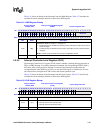
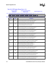
<8> IS8
GPIO[0] Edge Detect Interrupt Pending
0 – Interrupt NOT pending due to edge detect on GPIO[0].
1 – Interrupt pending due to edge detect on GPIO[0].
<7> IS7
Hardware UART Service Request Interrupt Pending
0 – Interrupt NOT pending due to Hardware UART Service Request.
1 – Interrupt pending due to Hardware UART Service Request.
<6:0> — Reserved
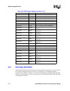
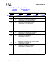
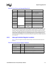
Table 4-37. List of First–Level Interrupts (Sheet 1 of 2)
Bit Position Source Unit # of Level 2 Sources Bit Field Description
IS<31>
Real-time clock
1 RTC equals alarm register.
IS<30> 1 One Hz clock TIC occurred.
IS<29>
Operating system
timer
1 OS timer equals match register 3.
IS<28> 1 OS timer equals match register 2.
IS<27> 1 OS timer equals match register 1.
IS<26> 1 OS timer equals match register 0.
IS<25> DMA controller 16 DMA Channel service request.
IS<24>
Synchronous Serial
Port
3 SSP service request.
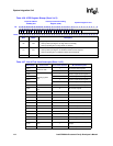
IS<23> MUlti Media Card 9 MMC status / error detection
IS<22> FFUART 5 x-mit, receive, error in FFUART.
IS<21> BTUART 5 x-mit, receive, error in BTUART
IS<20> STUART 4 x-mit, receive, error in STUART
IS<19> ICP 6 x-mit, receive, error in ICP.
IS<18> I2C 6 I2C service request.
IS<17> LCD controller 15 LCD controller service request.
IS<16> Network SSP 4 Network SSP service request
IS<15> Audio SSP 4 Audio SSP service request
IS<14> AC97 10 AC97 interrupt
IS<13> I2S 5 I2S interrupt
IS<12> Core 1
PMU (Performance Monitor)
interrupt
IS<11> USB 7 USB interrupt
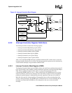
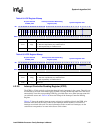
Table 4-36. ICPR Register Bitmap (Sheet 3 of 3)
Physical Address
0x40D0_0010
Interrupt Controller Pending
Register (ICPR)
System Integration Unit
Bit
31 30 29 28 27 26 25 24 23 22 21 20 19 18 17 16 15 14 13 12 11 10 9 8 7 6 5 4 3 2 1 0
IS31
IS30
IS29
IS28
IS27
IS26
IS25
IS24
IS23
IS22
IS21
IS20
IS19
IS18
IS17
IS16
IS15
IS14
IS13
IS12
IS11
IS10
IS9
IS8
IS7
Reserved
Reset
0 0 0 0 0 0 0 0 0 0 0 0 0 0 0 0 0 0 0 0 0 0 0 0 0 0 0 0 0 0 0 0
Bits Name Description


