3-40 Intel® PXA26x Processor Family Developer’s Manual
Clocks and Power Manager
3.7 Coprocessor 14: Clock and Power Management
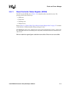
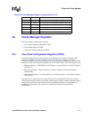
Coprocessor 14 contains two registers that control the power modes and sequences:
• CP14 register 6 - CCLKCFG Register
• CP14 register 7 - PWRMODE Register
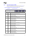
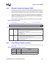
3.7.1 Core Clock Configuration Register (CCLKCFG)
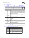
Use the CCLKCFG register (CP14 register 6), refer to Table 3-26, to enter the turbo mode and
frequency change sequence. To enter the mode or sequence, software executes the appropriate
function, as shown in Table 3-25. All core-initiated memory requests are completed before the
clocks and power manager initiates the desired mode or sequence.
To ensure that the turbo bit does not change when entering the frequency change sequence,
software must do a read-modify-write.
This is a read/write register. Ignore reads from reserved bits. Write zeros to reserved bits.
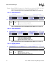
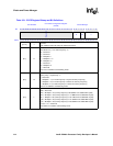
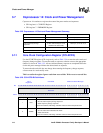
Table 3-25. Coprocessor 14 Clock and Power Management Summary
Function Data in Rd Instruction
Read CCLKCFG — MRC p14, 0, Rd, c6, c0, 0
Enter Turbo Mode TURBO = 1 MCR p14, 0, Rd, c6, c0, 0
Enter Frequency Change
Sequence
FCS = 1
(Turbo mode bit may be set or
cleared in the same write)
MCR p14, 0, Rd, c6, c0, 0
Enter Idle Mode M = 1 MCR p14, 0, Rd, c7, c0, 0
Enter Sleep Mode M = 3 MCR p14, 0, Rd, c7, c0, 0
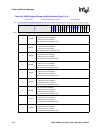
Table 3-26. CCLKCFG Bit Definitions
CP14
Register 6
CCLKCFG Clocks and Power Manager
Bit
31 30 29 28 27 26 25 24 23 22 21 20 19 18 17 16 15 14 13 12 11 10 9 8 7 6 5 4 3 2 1 0
Reserved
FCS
TURBO
Reset 0 0 0 0 0 0 0 0 0 0 0 0 0 0 0 0 0 0 0 0 0 0 0 0 0 0 0 0 0 0 0 0
[31:2] — Reserved
1FCS
FREQUENCY CHANGE SEQUENCE:
0 – Do not enter frequency change sequence
1 – Enter frequency change sequence
Cleared on hardware, watchdog, and GPIO reset and when sleep mode exits.
0TURBO
TURBO MODE:
0 – Do not enter turbo mode/exit turbo mode
1 – Enter turbo mode
Cleared on hardware, watchdog, and GPIO reset and when sleep mode exits.


