


Intel® PXA26x Processor Family Developer’s Manual 9-15
Inter-Integrated Circuit Bus Interface Unit
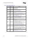
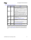
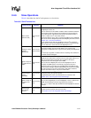
9.4.6 Slave Operations
Table 9-6 describes how the I
2
C unit operates as a slave device.
Table 9-6. Slave Transactions
I
2
C Slave Action
Mode of
Operation
Definition
Slave-receive
(default mode)
Slave-receive
only
I
2
C unit monitors all slave address transactions.
ICR[IUE] bit must be set.
I
2
C unit monitors bus for START conditions. When a START is detected,
the interface reads the first 8 bits and compares the most significant
seven bits with the 7-bit ISAR and the general call address (0x00). If
there is a match, the I
2
C unit sends an ACK.
If the first 8 bits are zero’s, this is a general call address. If the ICR[GCD]
bit is clear, both the ISR[GCAD] bit and the ISR[SAD] bit will be set. See
Section 9.4.7, “General Call Address”.
If the eighth bit of the first byte (R/nW bit) is low, the I
2
C unit stays in
slave-receive mode and the ISR[SAD] bit is cleared. If R/nW bit is high,
I
2
C unit switches to slave-transmit and ISR[SAD] bit is set.
Setting the Slave
Address
Detected bit
Slave-receive
Slave-transmit
Indicates the interface has detected an I
2
C operation that addresses the
processor including the general call address. The processor can
distinguish an ISAR match from a general call by reading the ISR[GCAD]
bit.
An interrupt is signalled, if enabled, after the matching slave address is
received and acknowledged.
Read one byte of
I
2
C Data from the
IDBR
Slave-receive
only
Data receive mode of I
2
C slave operation.
Eight bits are read from the serial bus into the shift register. When a full
byte is received and the ACK/NAK bit is completed, the byte is
transferred from the shift register to the IDBR.
Occurs when the ISR[IRF] bit is set and the ICR[TB] bit is clear. If
enabled, the IDBR Receive Full Interrupt is signalled to the CPU.
Software reads one data byte from the IDBR. When the IDBR is read,
the processor writes the desired ICR[ACKNAK] bit and sets the ICR[TB]
bit. This causes the I
2
C unit to stop inserting wait states and let the
master transmitter write the next piece of information.
Transmit
Acknowledge to
master-
transmitter
Slave-receive
only
As a slave-receiver, the I
2
C unit pulls the SDA line low to generate the
ACK pulse during the high SCL period.
ICR[ACKNAK] bit controls the ACK data the I
2
C unit drives. See
Section 9.4.3, “Inter-Integrated Circuit Acknowledge”.
Write one byte of
I
2
C data to the
IDBR
Slave-transmit
only
Data transmit mode of I
2
C slave operation.
Occurs when ISR[ITE] bit is set and ICR[TB] bit is clear. If enabled, the
IDBR Transmit Empty Interrupt is signalled to the processor.
The processor writes a data byte to IDBR and sets ICR[TB] bit to start the
transfer.
Wait for
Acknowledge
from master-
receiver
Slave-transmit
only
As a slave-transmitter, the I
2
C unit releases the SDA line to allow the
master-receiver to pull the line low for the ACK.
See Section 9.4.3, “Inter-Integrated Circuit Acknowledge”.