


Intel® PXA26x Processor Family Developer’s Manual 4-25
System Integration Unit
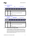
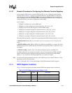
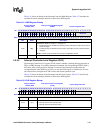
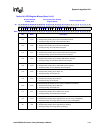
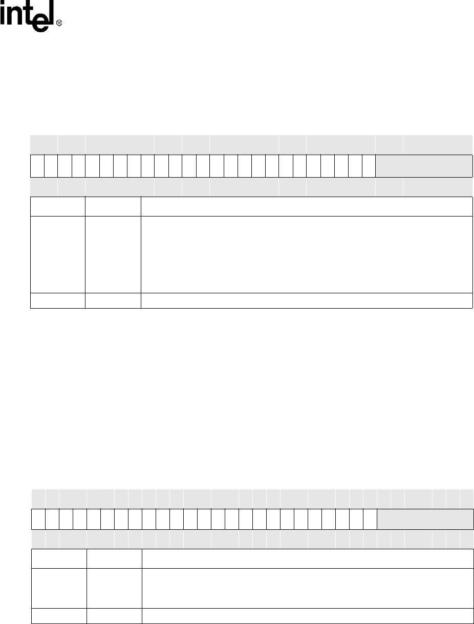
Table 4-31 shows the bitmap of the Interrupt Controller Mask Register. Table 4-37 describes the
available first-level interrupts and their location in the ICPR register.
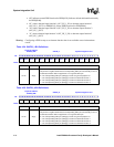
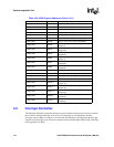
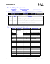
4.2.2.2 Interrupt Controller Level Register (ICLR)
The Interrupt Controller Level register (ICLR) controls whether a pending interrupt generates an
FIQ or an IRQ interrupt. If a pending interrupt is unmasked, the corresponding ICLR bit field is
decoded to select which processor interrupt is asserted. If the interrupt is masked, then the
corresponding bit in the ICLR has no effect. At reset the ICLR register is initialized to all zeros,
and software must configure the ICLR to reflect the normal operation value.
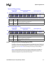
Table 4-32 shows the bitmap of the Interrupt Controller Level register. Table 4-37 describes the
available first-level interrupts and their location in the ICPR register.
Table 4-31. ICMR Register Bitmap
Physical Address
0x40D0_0004
Interrupt Controller Mask Register
(ICMR)
System Integration Unit
Bit
31 30 29 28 27 26 25 24 23 22 21 20 19 18 17 16 15 14 13 12 11 10 9 8 7 6 5 4 3 2 1 0
IM31
IM30
IM29
IM28
IM27
IM26
IM25
IM24
IM23
IM22
IM21
IM20
IM19
IM18
IM17
IM16
IM15
IM14
IM13
IM12
IM11
IM10
IM9
IM8
IM7
Reserved
Reset
0 0 0 0 0 0 0 0 0 0 0 0 0 0 0 0 0 0 0 0 0 0 0 0 ? ? ? ? ? ? ? ?
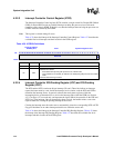
Bits Name Description
<31:8> IM[x]
INTERRUPT MASK ‘X’ (where x = 7 through 31):
0 – Pending interrupt is masked from becoming active (interrupts are NOT sent to CPU or
power manager).
1 – Pending interrupt is allowed to become active (interrupts are sent to CPU and power
manager).
NOTE: In IDLE mode, the IM bits are ignored if ICCR[DIM] is cleared.
<6:0> — Reserved
Table 4-32. ICLR Register Bitmap
Physical Address
0x40D0_0008
Interrupt Controller Level Register
(ICLR)
System Integration Unit
Bit
31 30 29 28 27 26 25 24 23 22 21 20 19 18 17 16 15 14 13 12 11 10 9 8 7 6 5 4 3 2 1 0
IL31
IL30
IL29
IL28
IL27
IL26
IL25
IL24
IL23
IL22
IL21
IL20
IL19
IL18
IL17
IL16
IL15
IL14
IL13
IL12
IL11
IL10
IL9
IL8
IL7
Reserved
Reset
0 0 0 0 0 0 0 0 0 0 0 0 0 0 0 0 0 0 0 0 0 0 0 0 ? ? ? ? ? ? ? ?
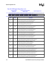
Bits Name Description
<31:8> IL[x]
INTERRUPT LEVEL ‘X’ (where x = 7 through 31):
0 – Interrupt routed to IRQ interrupt input.
1 – Interrupt routed to FIQ interrupt input.
<6:0> — Reserved