


Intel® PXA26x Processor Family Developer’s Manual 16-19
Network/Audio Synchronous Serial Protocol Serial Ports
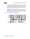
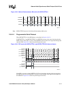
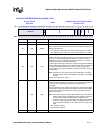
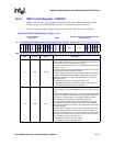
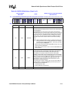
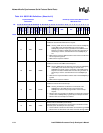
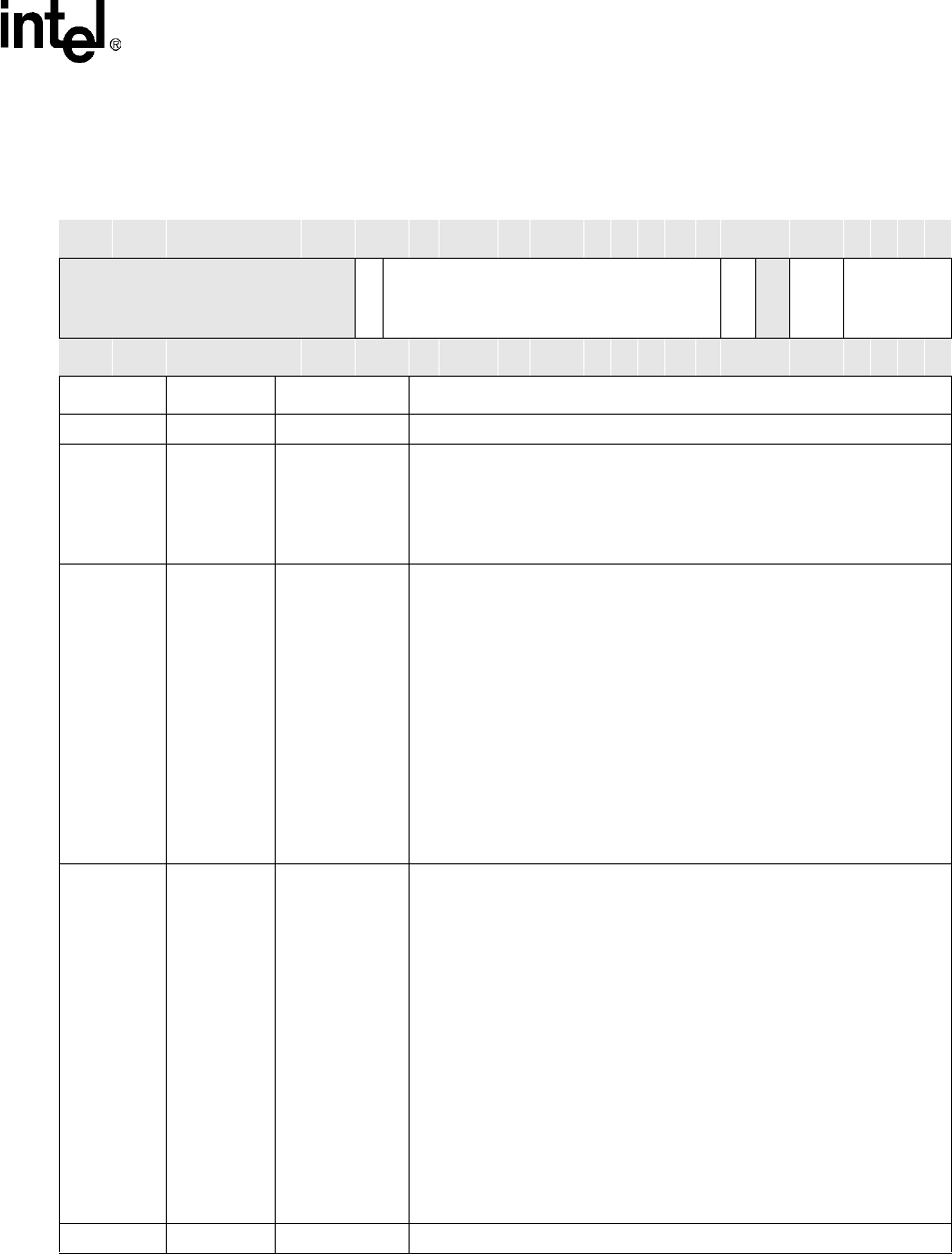
Table 16-3. SSCR0 Bit Definitions (Sheet 1 of 2)
Physical Address
Base+0x00
SSCR0
PXA26x processor family Network/Audio
SSP Serial Ports
Bit
31 30 29 28 27 26 25 24 23 22 21 20 19 18 17 16 15 14 13 12 11 10 9 8 7 6 5 4 3 2 1 0
Reserved
EDSS
SCR
SSE
Reserved
FRF
DSS
Reset ? ? ? ? ? ? ? ? ? ? ? 0 0 0 0 0 0 0 0 0 0 0 0 0 0 ? 0 0 0 0 0 0
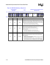
Bits Access Name Description
31:21 — — Reserved
20 R/W EDSS
EXTENDED DATA SIZE SELECT:
Used in conjunction with DSS to select the size of the data transmitted and
received by the SSP port.
0 – Pre-appended to the DSS value. Sets the DSS range from 4-16- bits.
1 – Pre-appended to the DSS value. Sets the DSS range from 17-32-bits.
19:8 R/W SCR
THE SERIAL CLOCK RATE:
Selects the bit rate of the SSP port when in master mode with respect to the
SSPSCLK (as defined by SSCR1[SCLKDIR]). The maximum bit rate is
3.6864 Mbps. The clock is divided by the value of SCR plus 1 (a range of 1
to 4096) to generate the serial clock (SSPSCLK).
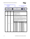
This field is ignored when the SSP port is a slave with respect to SSPSCLK
(defined by SSCR1[SCLKDIR]) and transmission data rates are determined
by the external device (Maximum of 13 MHz). At these fast baud rates,
using polled/interrupt mode is insufficient to keep the FIFO filled. You must
use DMA mode.
NOTE: Software must not change SCR when the SSPSCLK is enabled
because doing so causes the SSPSCLK frequency to immediately
change.
Serial bit rate = SSP Clock / (SCR + 1)
7 R/W SSE
SYNCHRONOUS SERIAL PORT ENABLE/DISABLE:
Enables and disables all SSP port operations. When the port is disabled, all
of its clocks can be stopped by programmers to minimize power
consumption.
When cleared during active operation, the SSP port is disabled immediately,
terminating the current frame being transmitted or received. Clearing SSE
resets the port FIFOs and the status bits; however, the SSP port control
registers are not reset.
NOTE: After reset or after clearing the SSE, software must ensure that the
SSCR1, SSITR, SSTO, and SSPSP control registers are properly
re-configured and that the SSSR register is reset before re-
enabling the SSP port by setting SSE. Also, SSE must be cleared
before re-configuring the SSCR0, SSCR1, or SSPSP registers; any
or all control bits in SSCR0 can be written at the same time as the
SSE.
0 – SSP operation disabled
1 – SSP operation enabled
6— —Reserved