


15-4 Intel® PXA26x Processor Family Developer’s Manual
MultiMediaCard Controller
Note: One- and three-byte data transfers are not supported with this controller. Data transfers of 10 or
more bytes are supported for stream writes only.
Refer to the MultiMediaCard System Specification, Version 2.1 for detailed information on MMC
and SPI modes of operation.
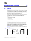
15.2 MultiMediaCard Controller Functional Description
The software must read and write the MMC controller registers and FIFOs to initiate
communication to a card.
The MMC controller is the interface between the software and the MMC bus. It is responsible for
the timing and protocol between the software and the MMC bus. It consists of control and status
registers, a 16-bit response FIFO that is eight entries deep, two 8-bit receive data FIFOs that are 32
entries deep, and two 8-bit transmit FIFOs that are 32 entries deep. The registers and FIFOs are
accessible by the software.
The MMC controller also enables minimal data latency by buffering data and generating and
checking CRCs.
Refer to Section 15.4, “MultiMediaCard Controller Operation” for examples.
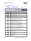
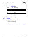
15.2.1 Signal Description
The MMC controller signals are MMCLK, MMCMD, MMDAT, MMCCS0, and MMCCS1.
Table 15-4 describes each signal’s function.
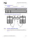
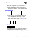
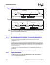
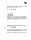
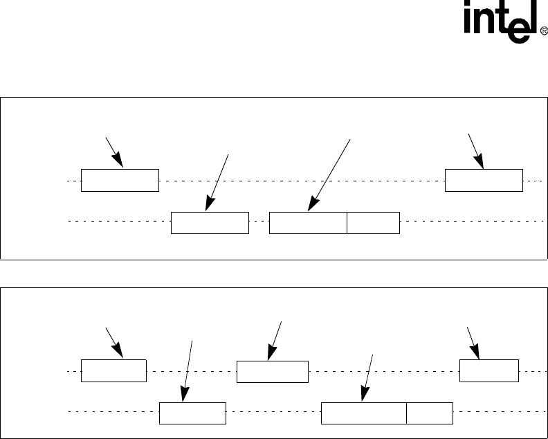
Figure 15-5. SPI Mode Read Operation
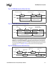
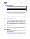
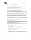
Figure 15-6. SPI Mode Write Operation
Command
MMCMD
MMDAT
Command
Response
from host to
data from card to
Next
Data Block CRC
from card to
Command
MMCMD
MMDAT
Command
Response
from host to
data from host to
new
Data Response Busy
from card to
Data Block
Data response