15-6 Intel® PXA26x Processor Family Developer’s Manual
MultiMediaCard Controller
address in the argument portion of the command token that is protected with a 7-bit CRC (see
Table 15-1). For a description of the identification process when multiple cards are connected to a
system, refer to the Card Identification Process as described in the MultiMediaCard System
Specification, Version 2.1.
There are five formats for the response token, including a no response token. The response token
length is 48 or 136 bits and may be protected with a 7-bit CRC. Details of the response token can
be found in the MultiMediaCard System Specification, Version 2.1.
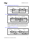
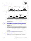
In write data transfers, the data is suffixed with a 5-bit CRC status token from the card. After the
CRC status token, the card may indicate that it is busy by pulling the MMDAT line low.
The start address for a read operation can be any random byte address in the valid address space of
the card memory. For a write operation, the start address must be on a sector boundary and the data
length must be an integer multiple of the sector length. A sector is the number of blocks that will be
erased during the write operation and is fixed for each MMC card. A block is the number of bytes
to be transferred.
The MMC mode supports the following data transfer modes:
• Single block read/write: in single block mode, a single block of data is transferred. The starting
address is specified in the command token of the read or write command used. The software
must set the block size in the controller by entering the number of bytes to be transferred in the
MMC_BLKLEN register. The data block is protected with a 16-bit CRC that is generated by
the sending unit and checked by the receiving unit. The CRC is appended to the data after the
last data bit is transferred.
• Multiple block read/write: in multiple block mode, multiple blocks of data are transferred.
Each block is the same length as specified by the software in the MMC_BLKLEN register.
The blocks of data are stored or retrieved from contiguous memory addresses starting at the
address specified in the command token. The software specifies the number of blocks to
transfer in the MMC_NOB register. Each data block is protected by appending a 16-bit CRC.
Multiple block data transfers are terminated with a stop transmission command.
• Stream read/write: in stream mode, a continuous stream of data is transferred. The starting
address is specified in the command token of the read or write command used. The data stream
is terminated with a stop transmission command. For write transfers, the stop transmission
command must be transmitted with the last six bytes of data. This ensures that the correct
amount of data is written to the card. For read transfers, the stop transmission command may
occur after the data transmission has occurred. There is no CRC protection for data in this
mode.
15.2.4.2 SPI Mode
SPI mode is an optional secondary communication protocol. In SPI mode, the MMCMD and
MMDAT lines are unidirectional and only single block data transfers are allowed. The MMCMD
signal is an output from the controller and sends the command token and write data to the MMC
card. The MMDAT signal is an input to the controller and receives the response token and read data
from the MMC card.
Note: When the card is in SPI mode, the only way to return to MMC mode is by toggling the power to the
card.
Card addressing is implemented with hardware chip selects, MMCCS1 and MMCCS0. All
command, response, and data tokens are 8-bits long and are transmitted immediately following the
assertion of the respective chip select.


