


7-22 Intel® PXA26x Processor Family Developer’s Manual
Liquid Crystal Display Controller
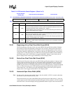
7.6.1.1 LCD Output Fifo Underrun Mask (OUM)
The output FIFO underrun mask (OUM) bit is used to mask interrupt requests that are asserted
whenever an output FIFO underrun error occurs. When OUM=0, underrun interrupts are enabled,
and whenever an output FIFO underrun (OU) status bit within the LCD Status Register (LCSR) is
set (one), an interrupt request is made to the interrupt controller. When OUM=1, underrun
interrupts are masked and the state of the underrun status bit (OU) is ignored by the interrupt
controller. Setting OUM does not affect the current state of the status bit or the LCD controller’s
ability to set and clear it, it only blocks the generation of the interrupt request. Output FIFO
underruns are more critical than input FIFO underruns, since output FIFO underruns will affect the
display.
7.6.1.2 Branch Mask (BM)
The LCD branch interrupt mask (BM) bit masks interrupt requests that are asserted after the LCD
controller has branched to a new set of frame descriptors. See Section 7.6.6 for details.
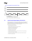
7.6.1.3 Palette DMA Request Delay (PDD)
The 8-bit palette DMA request delay (PDD) field selects the minimum number of internal bus
clock cycles to wait between the servicing of each DMA request issued while the on-chip palette is
loaded. When the palette is optionally loaded at the beginning of a frame, up to 512 bytes of data
may be accessed by the LCD’s DMAC. Using PDD allows other bus masters to gain access to
shared memory in between palette DMA loads. PDD can severely degrade LCD controller
performance if not used properly. You should leave PDD zero and add delay only when necessary.
PDD does not apply to the normal input FIFO DMA requests for frame buffer information, since
these DMA requests do not occur back-to-back. The input FIFO DMA request rate is a function of
the rate at which pixels are displayed on the screen.
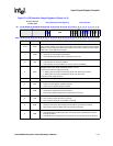
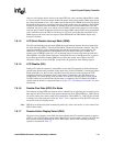
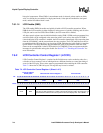
2SDS
SINGLE-/DUAL-PANEL DISPLAY SELECT (Section 7.6.1.12):
0 – Single-panel display enabled.
1 – Dual-panel display enabled.
SDS must be 0 in active mode (PAS=1).
1CMS
COLOR/MONOCHROME SELECT (Section 7.6.1.13):
0 – Color operation enabled.
1 – Monochrome operation enabled.
0ENB
LCD CONTROLLER ENABLE (Section 7.6.1.14):
0 – LCD controller disabled or in the process of quickly disabling.
1 – LCD controller enabled.
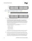
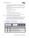
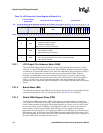
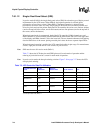
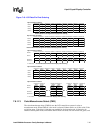
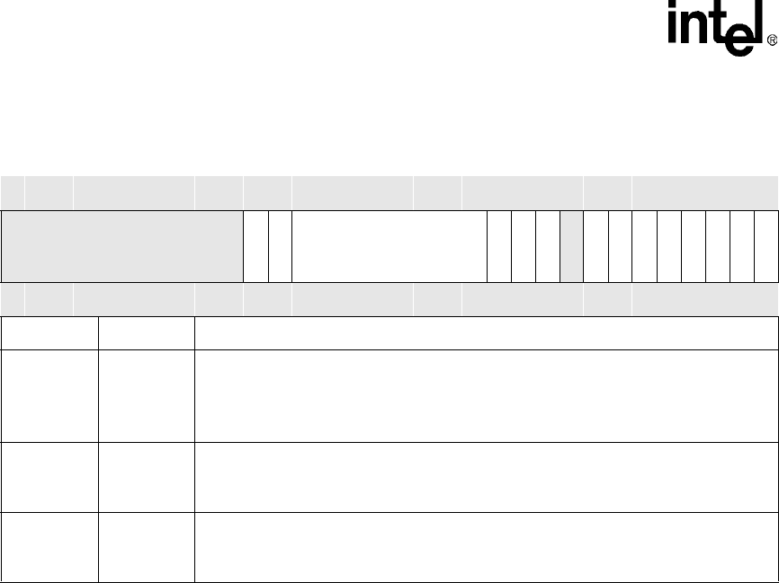
Table 7-2. LCD Controller Control Register 0 (Sheet 3 of 3)
Physical Address
0x4400_0000
LCD Controller Control Register 0 LCD Controller
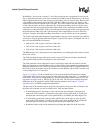
Bit
31 30 29 28 27 26 25 24 23 22 21 20 19 18 17 16 15 14 13 12 11 10 9 8 7 6 5 4 3 2 1 0
Reserved
OUM
BM
PDD
QDM
DIS
DPD
Reserved
PAS
EFM
IUM
SFM
LDM
SDS
CMS
ENB
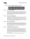
Reset X X X X X X X X X X X X 0 0 0 0 0 0 0 0 0 0 0 0 0 0 0 0 0 0 0 0
Bits Name Description