


Intel® PXA26x Processor Family Developer’s Manual 12-11
Universal Serial Bus Device Controller
12.4.1.1 When GPIOn and GPIOx are Different Pins
The GPIOn and GPIOx pins can be any GPIO pins. GPIOn must be a GPIO that can wake the
device from sleep mode. After a reset, GPIOx is configured as an input. This causes the UDC+ line
to float. GPIOn is configured to act as an input and to cause an interrupt on a rising or falling edge.
When an interrupt occurs, software must read the GPIOn pin to determine if the cable is connected.
The GPIOn pin is set to a 1 when the cable is connected and a 0 when the cable is disconnected.
When a USB connect is detected, software must enable the UDC peripheral and drive a 1 to the
GPIOx pin to indicate to the host PC that a high-speed USB device is connected. When a USB
disconnect is detected, software must configure the GPIOx pin as an input, configure the GPIOn
pin to detect a wake up event, and put the disconnected peripheral in sleep mode, if desired.
If software must put a peripheral in sleep mode, it configures the GPIOx pin as an input. This
causes the UDC+ line to float, which appears to be a disconnect to the host PC. The peripheral is
put in sleep mode. When the peripheral comes out of sleep mode, software must drive a 1 to the
GPIOx pin to indicate to the host PC that a high-speed USB peripheral is connected.
12.4.1.2 When GPIOn and GPIOx are the Same Pin
After a reset, GPIOn is configured to act as an input and to cause an interrupt on a rising or falling
edge. When an interrupt occurs, software must read the GPIOn pin to determine if the cable is
connected. GPIOn is set to a 1 when the cable is connected and a 0 when the cable is disconnected.
If a USB connect is detected, software must enable the UDC peripheral before the host PC sends
the first USB command. If a USB disconnect is detected, software must configure the GPIOn pin to
detect a wake up event and put the peripheral in sleep mode, if desired.
When GPIOn and GPIOx are the same pin, do not put a peripheral in sleep mode if the USB cable
is connected to the device. During sleep, the USB controller is in reset and does not respond to the
host PC. When it returns from sleep mode, the peripheral does not respond to its host-assigned
address.
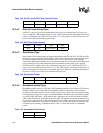
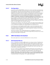
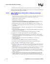
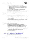
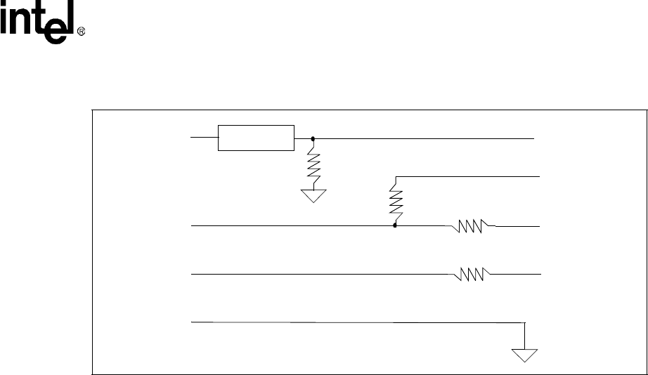
Figure 12-2. Self-Powered Device
USB 5V
USB D+
USB D-
USB GND
5 V to 3.3 V
1.5K
GPIOn
UDC D+
UDC D-
0 ohm
(optional)
0 ohm
(optional)
Board GND
470K
GPIOx