


4-38 Intel® PXA26x Processor Family Developer’s Manual
System Integration Unit
The trim procedure can counteract these factors by providing a highly accurate mechanism to
remove the variance and shifts from the manufacturing and static environment variables on an
individual system level. However, since this is a calibration solution, it is not a practical solution
for dynamic changes in the system and environment and can most likely only be done in a factory
setting due the equipment required.
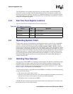
4.3.4 Real-Time Clock Register Locations
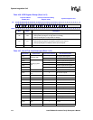
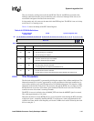
Table 4-43 describes the location of the real-time clock registers.
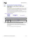
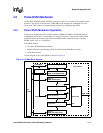
4.4 Operating System Timer
The processor contains a 32-bit operating system (OS) timer that is clocked by the 3.6864-MHz
oscillator. The Operating System Count register (OSCR) is a free running up-counter. The OS
timer also contains four 32-bit match registers (OSMR3, OSMR2, OSMR1, OSMR0). You can
read and write to each register. When the value in the OSCR is equal to the value within any of the
match registers, and the interrupt enable bit is set, the corresponding bit in the OSSR is set. These
bits are also routed to the interrupt controller where they can be programmed to cause an interrupt.
OSMR3 also serves as a watchdog match register that resets the processor when a match occurs
provided the OS Timer Watchdog Match Enable Register (OWER) is set. You must initialize the
OSCR and OSMR registers and clear any set status bits before the FIQ and IRQ interrupts are
enabled within the CPU.
4.4.1 Watchdog Timer Operation
You may also use the OSMR3 as a watchdog compare register. This function is enabled by setting
OWER[0]. When a compare against this register occurs and the watchdog is enabled, reset is
applied to the processor and most internal states are cleared. Internal reset is asserted for 256
processor clocks and then removed, allowing the processor to boot. See Section 3.4.2, “Watchdog
Reset” on page 3-7 for details on reset functionality.
The following procedure is suggested when using OSMR3 as a watchdog
– each time the operating
system services the register:
1. The current value of the counter is read.
2. An offset is then added to the read value. This offset corresponds to the amount of time before
the next time-out (care must be taken to account for counter wraparound).
3. The updated value is written back to OSMR3.
The OS code must repeat this procedure periodically before each match occurs. If a match occurs,
the OS timer asserts a reset to the processor.
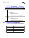
Table 4-43. RTC Register Addresses
Address Name Description
0x4090_0000 RCNR RTC count register
0x4090_0004 RTAR RTC alarm register
0x4090_0008 RTSR RTC status register
0x4090_000C RTTR RTC trim register