


4-26 Intel® PXA26x Processor Family Developer’s Manual
System Integration Unit
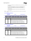
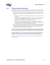
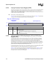
4.2.2.3 Interrupt Controller Control Register (ICCR)
The Interrupt Controller Control register (ICCR) contains a single control bit, Disable IDLE Mask
(DIM). In normal IDLE mode any enabled interrupt can bring the processor out of idle mode
regardless of the value in ICMR. If this bit is set, then the interrupts that can bring the processor out
of IDLE mode are defined by the ICMR.
Note: This register is cleared during all resets.
Table 4-33 shows the bitmap of the Interrupt Controller Control Register. Table 4-37 describes the
available first-level interrupts and their location in the ICPR register.
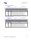
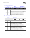
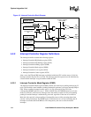
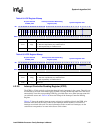
4.2.2.4 Interrupt Controller IRQ Pending Register (ICIP) and FIQ Pending
Register (ICFP)
The ICIP and the ICFP contain one bit per interrupt (25 total.) These bits indicate an interrupt
request has been made by a unit. Inside the interrupt service routine, read the ICIP and ICFP to
determine the interrupt source. In general, software then reads status registers within the
interrupting device to determine how to service the interrupt. Bits within the ICPR (see Section
4.2.2.5 on page 4-27) are read only, and represent the logical OR of the status bits in the ICIP and
ICFP for a given interrupt. Once an interrupt has been serviced, the handler writes a one to the
required status bit, clearing the pending interrupt at the source.
Clearing the interrupt status bit at the source, automatically clears the corresponding ICIP or ICFP
flag, provided there are no other interrupt status bits set within the source unit.
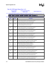
Table 4-34 shows the bitmap of the Interrupt Controller IRQ Pending Register. Table 4-35 shows
the bitmap of the Interrupt FIQ Pending Register. Table 4-37 describes the available first-level
interrupts and their location in the ICPR register.
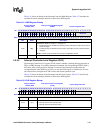
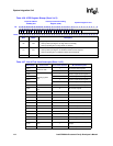
Table 4-33. ICCR Bit Definitions
Physical Address
0x40D0_0014
ICCR System Integration Unit
Bit
31 30 29 28 27 26 25 24 23 22 21 20 19 18 17 16 15 14 13 12 11 10 9 8 7 6 5 4 3 2 1 0
Reserved
DIM
Reset ? ? ? ? ? ? ? ? ? ? ? ? ? ? ? ? ? ? ? ? ? ? ? ? ? ? ? ? ? ? ? 0
Bits Name Description
<31:1> — Reserved
<0> DIM
DISABLE IDLE MASK:
0 – All enabled interrupts bring
the processor out of IDLE mode.
1 – Only enabled and unmasked (as defined in the ICMR) bring the processor out of IDLE
mode.
This bit is cleared during all resets.