Intel® PXA26x Processor Family Developer’s Manual 4-33
System Integration Unit
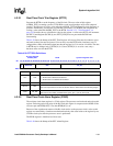
4.3.2.1 Real-Time Clock Trim Register (RTTR)
Program the RTTR to set the frequency of the Hz clock. The reset value of this register
(0x0000_7FFF) (assuming a perfect 32.768-KHz crystal) would produce an Hz-clock output of
exactly 1 Hz. However, by using values other than 0x0000_7FFF, a different Hz-clock frequency is
possible. Additionally, you may use a crystal that is not exactly 32.768 KHz and compensate by
writing a value other than 0x0000_7FFF to the RTTR. Section 4.3.3, “Trim Procedure” on
page 4-35 describes how to calculate the value in this register. A write to the RTTC will increment
the RTC Count Register (RCNR) by one. RTTC[LCK] does not prevent the RCNR from
incrementing.
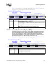
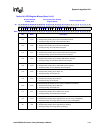
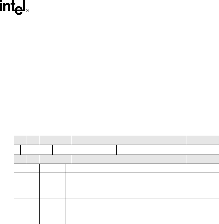
Table 4-39 shows the bitmap of the RTC Trim Register. All reserved bits must be written to zeros
and reads to these bits must be ignored. You can only reset the RTTR with a hardware reset. To
safeguard the validity of the data written into the trim register, bit 31 is used as a Lock Bit. The data
in RTTR may be changed only if RTTR(31) is 0. Once, RTTR(31) is set to be a one, only a
hardware reset can clear the RTTR.
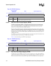
4.3.2.2 Real-Time Clock Alarm Register (RTAR)
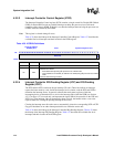
The real-time clock alarm register is a 32-bit register. The processor can both read and write to this
register. Following each rising edge of the Hz clock, this register is compared to the RCNR. If the
two are equal and RTSR[ALE] is set, then RTSR[AL] is set.
Because of the asynchronous nature of the Hz clock relative to the processor clock, writes to this
register are controlled by a hardware mechanism that delays the actual write to the register by two
32-KHz-clock cycles after the processor store is performed.
The RTAR register is initialized to 0x0 at reset.
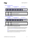
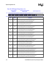
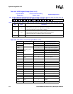
Table 4-40 shows the bitmap of the RTC Alarm Register.
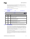
Table 4-39. RTTR Bit Definitions
Physical Address
0x4090_000C
RTTR System Integration Unit
Bit
31 30 29 28 27 26 25 24 23 22 21 20 19 18 17 16 15 14 13 12 11 10 9 8 7 6 5 4 3 2 1 0
LCK
Reserved DEL CK_DIV
Reset
0 ? ? ? ? ? 0 0 0 0 0 0 0 0 0 0 0 1 1 1 1 1 1 1 1 1 1 1 1 1 1 1
Bits Name Description
<31> LCK
TRIM VALUE LOCKING BIT:
0 – RTTR value is allowed to be altered.
1 – RTTR value is not allowed to be altered.
<30:26> — Reserved
<25:16> DEL
TRIM DELETE COUNT:
This value represents the number of 32-KHz clocks to delete when clock trimming begins.
<15:0> CK_DIV
CLOCK DIVIDER COUNT:
This value is the number of 32-KHz-clock cycles, plus 1, per Hz clock cycle.


