Intel® PXA26x Processor Family Developer’s Manual 15-7
MultiMediaCard Controller
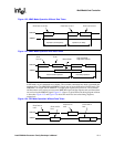
The command token is protected with a 7-bit CRC. The card always sends a response to a
command token. The response token has four formats, including an 8-bit error response. The length
of the response tokens is one, two, or five bytes.
SPI mode offers a non protected mode. In this mode, CRC bits of the command, response, and data
tokens are still required in the tokens but these bits are ignored by the card and the controller.
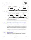
In write data transfers, the data is suffixed with an 8-bit CRC status token from the card. As in
MMC mode, the card may indicate that it is busy by pulling the MMDAT line low after the status
token. In read data transfers, the card may respond with the data or a data error token one byte long.
15.2.5 Error Detection
The MMC controller detects the following errors on the MMC bus and reports them in the status
register (MMC_STAT):
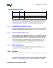
• Response CRC error: a CRC error was calculated on the command response.
• Response time out: the response did not begin before the specified number of clocks.
• Write data CRC error: the card returned a CRC status error on the data.
• Read data CRC error: a CRC error was calculated on the data.
• Read time out: the read data operation did not begin before the specified number of clocks.
• SPI data error: a read data error token was detected In SPI mode.
15.2.6 Interrupts
The MMC controller generates interrupts to signal the status of a command sequence. The software
is responsible for masking the interrupts appropriately, verifying the interrupts, and performing the
appropriate action as necessary.
Interrupts and masking are described in sections Section 15.5.11, “MMC_I_MASK Register” and
Section 15.5.12, “MMC_I_REG Register”. The CMDAT[DMA_EN] bit will also mask the
MMC_I_MASK[RXFIFO_RD_REQ] and MMC_I_MASK[TXFIFO_WR_REQ] interrupt bits.
15.2.7 Clock Control
Both the MMC controller and the software can control the MMC bus clock (MMCLK) by turning
it on and off. This helps to control the data flow to prevent under runs and overflows and also
conserves power. The software can also change the frequency at any time to achieve the maximum
data transfer rate specified for a card’s identification frequency.
The MMC controller has an internal frequency generator that may start, stop, and divide the MMC
bus clock. The software may start and stop the clock by setting the appropriate bits in the
MMC_STRPCL register. The MMCLK frequency is controlled by the value written in the
MMC_CLKRT register.
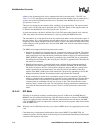
To write any MMC controller register for the next command sequence, software must:
1. Stop the clock.
2. Write the registers.


