Intel® PXA26x Processor Family Developer’s Manual 6-53
Memory Controller
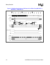
• tAH = Address hold after nWE deasserted = 1 MEMCLK
• nWE high time between burst beats = 2 MEMCLKs
6.8.5 Variable Latency I/O (VLIO) Interface Overview
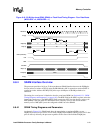
VLIO read accesses differ from SRAM read accesses in that the nOE toggles for each beat of a
burst. The first nOE assertion occurs two memory cycles after the assertion of the chip select
nCS<x>. Also, for Variable Latency I/O writes, nPWE is used instead of nWE so SDRAM
refreshes can be executed while performing the VLIO transfers. Variable Latency I/O is selected by
programming the MSCx[RTx] bits as 0b100.
Both reads and writes for VLIO differ from SRAM in that the processor samples the data-ready
input, RDY. The RDY signal is level sensitive and goes through a two-stage synchronizer on input.
When the internal RDY signal is high, the I/O device is ready for data transfer. This means that for
a transaction to complete at the minimum assertion time for either nOE or nPWE (RDF+1), the
RDY signal must be high two clocks prior to the minimum assertion time for either nOE or nPWE
(RDF-1). Data will be latched on the rising edge of MEMCLK once the internal RDY signal is high
and the minimum assertion time of RDF+1 has been reached. Once the data has been latched, the
address may change on the next rising edge of MEMCLK or any cycles thereafter. The nOE or
nPWE signal will de-assert one MEMCLK after data is latched. Before a subsequent data beat,
nOE or nPWE remains deasserted for RDN+1 memory cycles. The chip select and byte selects,
DQM[3:0], remain asserted for one memory cycle after the burst’s final nOE or nPWE deassertion.
For both reads and writes from/to VLIO, a DMA mode exists that does not increment the address to
the VLIO, which will allow port-type VLIO chips to interface to the processor. See
DCMDx[INCSRCADDR] and DCMDx[INCTRGADDR] in Table 5-12, “DCMDx Register
Bitmap and Bit Definitions” on page 5-24.
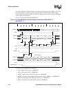
For writes to VLIO, if all byte enables are turned off, masking out the data, DQM = 1111, the write
enable is suppressed (nPWE = 1) for this write beat to VLIO. This can result in a period when nCS
is asserted, but neither nOE nor nPWE is asserted (this happens when there is a write of 1 beat to
VLIO, but all byte enables are turned off).
6.8.5.1 Variable Latency I/O Timing Diagrams and Parameters
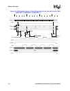
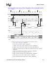
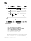
Figure 6-18 shows the timing for Variable Latency I/O reads and Figure 6-19 shows the timing for
Variable Latency I/O writes.


