


Intel® PXA26x Processor Family Developer’s Manual 13-11
AC97 Controller Unit
Note: Slot requests for slots 3 and 4 are always set or cleared in tandem (both set or both cleared).
13.4.2.3 Slot 2: Status Data Port
The status data port delivers 16-bit control register read data.
Note: If slot 2 is tagged invalid, the ACUNIT fills the entire slot with zeroes.
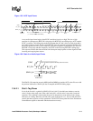
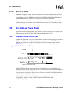
13.4.2.4 Slot 3: PCM Record Left Channel
Audio input frame slot 3 is the ACUNIT codec left channel output.
The ACUNIT transmits its ADC output data (MSB first) and fills any trailing non-valid bit
positions with zeroes to fill its 20-bit time slot.
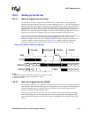
13.4.2.5 Slot 4: PCM Record Right Channel
Audio input frame slot 4 is the ACUNIT codec right-channel output.
The ACUNIT transmits its ADC output data (MSB first), and fills any trailing non-valid bit
positions with zeroes to fill its 20-bit time slot.
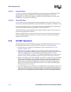
13.4.2.6 Slot 5: Optional Modem Line Codec
Audio input frame slot 5 contains MSB justified modem ADC output data (if the line codec is
supported).
The processor supports a 16-bit ADC output resolution for the optional modem.
13.4.2.7 Slot 6: Optional Dedicated Microphone Record Data
Audio input frame slot 6 is an optional third PCM system-input channel available for dedicated use
by a microphone. This input channel supplements a true stereo output that would enable a more
precise echo-cancellation algorithm for speakerphone applications.
The ACUNIT only supports 16-bit resolution for the mic-in channel.
13.4.2.8 Slots 7-11: Reserved
Audio input frame slots 7-11 are reserved for future use and the ACUINT ignores them.
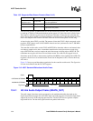
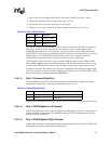
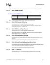
Table 13-6. Input Slot 2 Bit Definitions
Bit Name Description
Bit(19:4) Control register read data Filled with zeroes if AC97 tags it invalid
Bit(3:0) Reserved Filled with zeroes