


4-16 Intel® PXA26x Processor Family Developer’s Manual
System Integration Unit
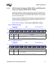
4.1.3.5 GPIO Edge Detect Status Register (GEDR)
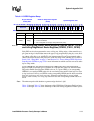
The GPIO Edge Detect Status registers (GEDR0, GEDR1, GEDR2) contain a total of 90 status bits
that correspond to the 90 GPIO pins. When an edge detect occurs on a pin that matches the type of
edge programmed in the GRER or GFER registers, the corresponding status bit is set in GEDR.
Once a GEDR bit is set by an edge event the bit remains set until the user clears it by writing a one
to the status bit. Writing a zero to a GEDR status bit has no effect.
Each edge detect that sets the corresponding GEDR status bit for GPIO[89:0] can trigger an
interrupt request. GPIO[89:2] together form a group that can cause one interrupt request to be
triggered when any one of GEDR[89:2] are set. GPIO[0] and GPIO[1] cause independent first-
level interrupts. Refer to Section 4.2, “Interrupt Controller” on page 4-22, for a description of the
programming of GPIO interrupts.
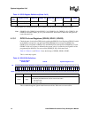
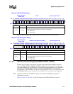
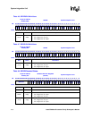
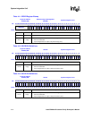
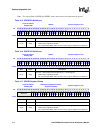
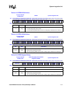
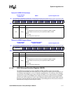
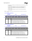
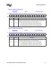
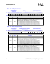
Table 4-21 through Table 4-23 show the bitmaps of the GPIO Edge Detect Status registers.
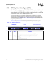
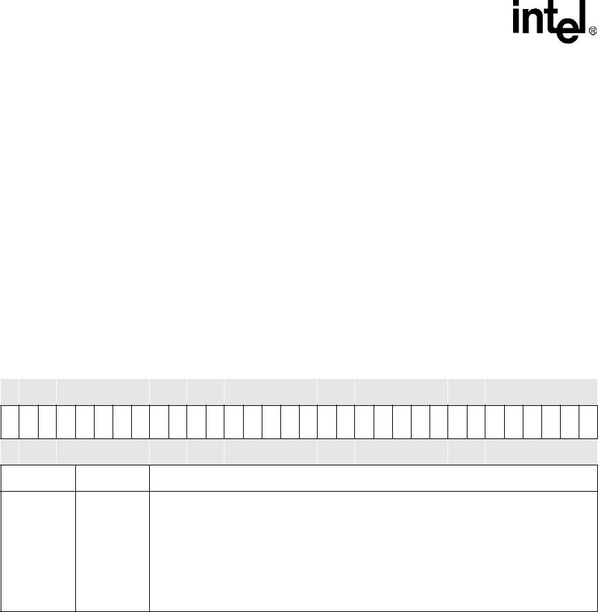
Table 4-21. GEDR0 Bit Definitions
Physical Address
0x40E0_0048
GEDR0 System Integration Unit
Bit
31 30 29 28 27 26 25 24 23 22 21 20 19 18 17 16 15 14 13 12 11 10 9 8 7 6 5 4 3 2 1 0
ED31
ED30
ED29
ED28
ED27
ED26
ED25
ED24
ED23
ED22
ED21
ED20
ED19
ED18
ED17
ED16
ED15
ED14
ED13
ED12
ED11
ED10
ED9
ED8
ED7
ED6
ED5
ED4
ED3
ED2
ED1
ED0
Reset 0 0 0 0 0 0 0 0 0 0 0 0 0 0 0 0 0 0 0 0 0 0 0 0 0 0 0 0 0 0 0 0
Bits Name Description
<31:0> ED[x]
GPIO PIN ‘X’ EDGE DETECT STATUS (where x = 0 through 31):
READ
0 – No edge detect has occurred on pin as specified in GRER or GFER.
1 – Edge detect has occurred on pin as specified in GRER or GFER.
WRITE
0 – No effect.
1 – Clear edge detect status field.