


9-22 Intel® PXA26x Processor Family Developer’s Manual
Inter-Integrated Circuit Bus Interface Unit
13. Read IDBR data.
14. Initiate STOP abort condition (STOP with no data transfer).
Set ICR[MA]
Note: If a NAK is not sent in step 11, the next transaction must involve another data byte read.
9.7 Glitch Suppression Logic
The I
2
C unit has built-in glitch suppression logic that suppresses glitches of 60ns or less. This is
within the 50ns glitch suppression specification.
9.8 Reset Conditions
Software must ensure that the I
2
C unit is not busy before it asserts a reset. Software must also
ensure that the I
2
C bus is idle when the unit is enabled after reset. When directed to reset, the I
2
C
unit, except for ISAR, returns to the default reset condition. ISAR is not affected by a reset.
When the ICR[UR] bit is set, the I
2
C unit resets but the associated I
2
C MMRs remain intact. When
resetting the I
2
C unit with the ICR’s unit reset, use the following guidelines:
1. Set the reset bit in the ICR register and clear the remainder of the register.
2. Clear the ISR register.
3. Clear reset in the ICR.
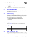
9.9 Register Definitions
The registers in Table 9-8 are associated with the I
2
C unit and are located in the processor
peripheral memory-mapped address space.
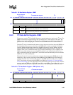
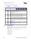
9.9.1 I
2
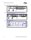
C Bus Monitor Register- IBMR
The I
2
C Bus Monitor Register (IBMR) tracks the status of the SCL and SDA pins. The values of
these pins are recorded in this read-only IBMR so software can determine when the I
2
C bus is hung
and the I
2
C unit must be reset.
Table 9-8. I
2
C Register Definitions
Register Addresses Name Section
0x4030 1680 IBMR Section 9.9.1, “I2C Bus Monitor Register- IBMR”
0x4030 1688 IDBR Section 9.9.2, “I2C Data Buffer Register- IDBR”
0x4030 1690 ICR Section 9.9.3, “I2C Control Register- ICR”
0x4030 1698 ISR Section 9.9.4, “I2C Status Register”
0x4030 16A0 ISAR Section 9.9.5, “I2C Slave Address Register- ISAR”