Intel® PXA26x Processor Family Developer’s Manual 2-3
System Architecture
2.3 Intel® XScale™ Microarchitecture Implementation
Options
The processor incorporates the Intel® XScale™ microarchitecture. This core contains
implementation options which an Application Specific Standard Product (ASSP) may elect to
implement or omit. This section describes these options.
Most of these options are specified within the coprocessor register space. The processor does not
implement any coprocessor registers beyond those defined in the Intel® XScale™
Microarchitecture for the Intel® PXA255 Processor User’s Manual. The coprocessor registers
which are ASSP specific, as stated in the Intel® XScale™ Microarchitecture for the Intel®
PXA255 Processor User’s Manual, are defined in the following sections.
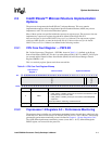
2.3.1 CPU Core Fault Register — PSFS Bit
Bit 5 of the Coprocessor 7 Register 4 – PSFS Bit, shown in Table 2-1, is defined as the Power
Source Fault Status (PSFS) bit. This bit is set when either nVDD_FAULT or nBATT_FAULT pins
are asserted and the Imprecise Data Abort Enable (IDAE) bit in the Power Manager Control
Register (PMCR) is set.
This is a read-only register. Ignore reads from reserved bits.
2.3.2 Coprocessor 14 Registers 0-3 – Performance Monitoring
The processor does not define any performance monitoring features beyond those called out in the
Intel® XScale™ Microarchitecture for the Intel® PXA255 Processor User’s Manual. The interrupt
generated by performance monitoring events is defined in Chapter 4, “System Integration Unit”.
The ASSP defined performance monitoring events (events 0x10 – 0x17), defined through the
PMNC register, are reserved for the processor.
Table 2-1. CPU Core Fault Register Bitmap
Coprocessor 7
Register 4
CPU Core Fault System Architecture
Bit
31 30 29 28 27 26 25 24 23 22 21 20 19 18 17 16 15 14 13 12 11 10 9 8 7 6 5 4 3 2 1 0
Reserved
PSFS
Reserved
Reset 0 0 0 0 0 0 0 0 0 0 0 0 0 0 0 0 0 0 0 0 0 0 0 0 0 0 0 0 0 0 0 0
[31:6] — Reserved
5 PSFS
POWER SOURCE FAULT STATUS:
0 – nVDD_FAULT or nBATT_FAULT pin has not been asserted since it was
last cleared by a reset or the CPU.
1 – nVDD_FAULT or nBATT_FAULT pin was asserted and PMCR[IDAE]
equals one.
Cleared by hardware, watchdog, and GPIO Resets.
[4:0] — Reserved


