


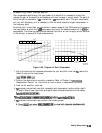
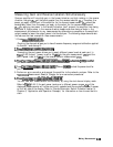

Measuring Gain Compression
Gain compression occurs when the input power of an amplifier is increased to a level that
reduces the gain of the amplifier and causes a nonlinear increase in output power. The point at
which the gain is reduced by 1
dB
is called the 1
dB
compression point. The gain compression
will vary with frequency, so it is necessary to find the worst case point of gain compression in
the frequency band.
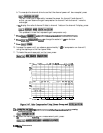
Once that point is identified, you can perform a power sweep of that CW frequency to measure
the input power at which the 1
dB
compression occurs and the absolute power out (in
dBm)
at
compression. The following steps provide detailed instruction on how to apply various features
of the analyzer to accomplish these measurements.
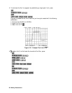
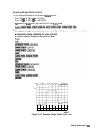
(0)
Input Power
(dBm)
(b)
Input Power
(dam)
pb697d
Figure 2-46. Diagram of Gain Compression
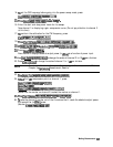
1. Set up the stimulus and response parameters for your amplifier under test.
To
reduce the
effect of noise on the trace, press:
2. Perform the desired error correction procedure. Refer to Chapter 5,
“Optimizmg
Measurement Results,” for instructions on how to make a measurement correction.
3. Hook up the amplifier under test.
4.
Tb
produce a normalized trace that represents gain compression, perform either step 5
or step 6. (Step 5 uses trace math and step 6 uses uncoupled channels and the display
function
~~~~~~~~~~~.)
:..:
.A...
.::.:.:.i..;;.;;.;;..;;;;;
ii
i
ii.i..:::
.
i.
.z..:..
.,...,............
5.
fiess
t-1
~~~~~~~~~~~
@$&&@
to
produce
a
nom&&
trace.
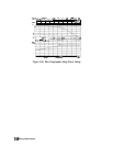
6.
lb
produce a normalized trace, perform the following steps:
Making Measurements
2-56