


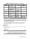

Calibration Standards
The quality of the error-correction is limited by two factors: (1) the difference between the
model of the calibration standards and the actual electrical characteristics of those standards,
and (2) the condition of the calibration standards. lb make the highest quality measurement
calibration, follow the suggestions below:
H
Use the correct standard model.
n Inspect the calibration standards
n
Clean the calibration standards,
H
Gauge the calibration standards.
n
Use correct connection techniques.
If you want to use calibration standards other than the default sets, you must change the
standard model. (Refer to “Modifying Calibration Kit Standards” located later
in
this chapter.)
After you enter the mathematical model for the new calibration standards, the analyzer can
then use the model that corresponds to the new standards
Compensating
for the Electrical Delay of calibration Standards
Short and open calibration standards in the
3.5~mm,
2.4~mm,
and
2.92~mm
connector types
have a certain amount of electrical delay. The analyzer compensates for this delay by offsetting
the calibration results by the total amount of electrical delay caused by the calibration standard
in both the forward and reverse direction. As a result, if these standards are measured after a
calibration, they will not appear to be “perfect” shorts or opens. This is an indication that
gour
UTZ.@J~
is
working
proper&
and that it has successfully performed a calibration.
Note
If you enter the opposite amount of electrical delay that was used by the
analyzer during calibration, then the short calibration standard
will
appear
to be “perfect.”
The open calibration standard has additional phase shift
caused by fringing capacitance. See “Calibration Considerations” in Chapter 6,
“Application and Operation Concepts
n
Chrifyhg
We-N
Connector Sex
When you are performing error-correction for a system that has type-N test port connectors,
the softkey menus label the sex of the test port connector--not the calibration standard
coMe~or.
For
example,
the
label
~~~~~~~~~~
refers
to
the
shod
that
fl
be coMe&ed to the
female
test
port.
When to Use Interpolated Error-Correction
You may want to use interpolated error-correction when you choose a subset of a frequency
range that you already corrected, when you change the number of points, or when you change
to CW. This feature also allows you to change the parameters in a
2-port
correction, such as IF
bandwidth, power, or sweep time. The analyzer calculates the systematic errors from the errors
of the original correction.
The quality of the interpolated error-correction depends on the amount of phase shift and
amplitude change of the error coefficients between measurement points If the phase shift
is cl800 per five measurement points, the interpolated error-correction can be a great
improvement over uncorrected measurement.
;;;;;;,. .
.
.
.
.
.
.
.
.
.
.
..T .
.
.
..c
:;:~~~,:;:~~~,~~:,:~,~;:::~~,,?,:.~~~.. ..z.f<>j;
.
.
.
.
.
.
.
.
.
.
.
.
.
.
.
.
.
.
.
.
_
.
.
.
.
.
.,.
‘l’b
a&iv&e
interpolated
measurement
cofle&ion,
press
a
~~~~~~
~~~~~~.~~~~1.
._;;;;;=;;,.;..:................._i
..A...
.
.
.
.
..s...>....>
ii
i.....<..Z
..A,. .:i...c
,........_..._.............
-
.
.
.
.
.
.
.
.._....................~..
.::
~:::::::
When interpolation is in use, the notation CA will appear on the analyzer display.
6-6 Optimizing Measurement Results