


/ . .../
.;,.,.,.,.,.,.,.,.
,.;.
. . . . . . . . .
;..,.,.,.,.,..~~..
..:..-
..~
_....
~~~,;~~~~~~~~~~~~:
;%l
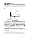
is selected when the desired measurement impedance differs from the
i
.;:
i..
“../;:
:.
:..::
.i.,.;;;;,-d:.:
impedance of the line standard. This requires a knowledge of the exact value of the
Z0
of
the line. The system reference impedance is set using
B”J$:G$fl~
under the calibration menu.
.:
..::
..:::...
Fe
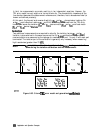
actual impedance of the line is set by entering the real part of the line impedance as the
,....
/
.::.:
. . . . .
::,:..
~~~~~~:~~; within the
define
standard menu. For example, if the line was known to have
i..:
. . . . .
..i....
.:::::
I
. . . .
. . . .
..A
(.~.;;..~...:~~~~~.:.:.~~:
a characteristic impedance of 51
Q
(~~~~~~~~~ = 51
Q),
it could still be used to calibrate
.,.,
for
a
50
Q
measurement
(#$$
I:.#@:
=
50
a).
After a calibration, all measurements would be
referenced to 50
Q,
instead of 51
Q.
When the line standard is remeasured, the center of the
::.
::s,
.:3:;
,;..j,,:w,
Smith chart is at the current value of
:$m$@’
(in this case, 50
Q).
Since only one value of
offset
ZO
can be selected for the line standard, the value of
ZO
should be a constant value over
the
frequency range of interest in order to be meaningful.
:
,:
:,.,.,.
.
.
.
.
.
.
.
.
.
.
.
.
,..............
_
,.....
_
,.............:.
,,..,.,.,
_..:
/,.,,,
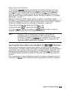
me
location
of the reference
plane
is
d&e&&
by
the
xl&,ion
of'~~.~~~~~~
a&
.:
T
~.~.~.~...~..i
ii:
;.:i:::.~......~.::~..~:~~~......::.
:'.;'::$.:$<zc
.!
:
c:<<<
.,
i
.:
/::.
.
.
.
.
.
.
.
...........i;;TT
..A.
.:..:.
. ""'::::'::.:::...:
'.,,
I
,,.
__,,,.
.,..,..,,*,,
~~~~~~.
By
d&a&,
the reference plane
is
set
Mththeth
standard
wK&
*
must have a known insertion phase or electrical length. If a non-zero length thru is specified
to have zero delay, the reference plane will be established in the middle of the thru. The
reflect standard may be used to set the reference plane instead of the thru provided the phase
response (offset delay, reactance values and standard type) of the reflect standard is known
and is specified in the calibration kit
dehnition.
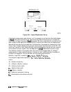
Note
Dispersion Effects
Dispersion occurs when a transmission medium exhibits a variable propagation
or phase velocity as a function of frequency. The result of dispersion is a
non-linear phase shift versus frequency, which leads to a group delay which
is not constant. Fortunately, the TRL calibration technique accounts for
dispersive effects of the test fixture up to the calibration plane, provided that:
1. The thru (zero or non-zero length) is defined as having zero electrical length
/
:
i....::...
. . . . . .
..a
.i
..L . . . . . . . . . . . .
..A
. . . . . .
..a..
I.
.
..i
il .i..
. . . . . .
and is used to set the reference plane
(~~~~~~~:..;~~~).
.”
..-.............-.
-
_.......
2. The transmission lines used as calibration standards have identical dispersion
characteristics (i.e., identical height, width and relative dielectric constant).
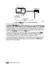
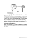
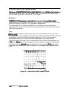
When a non-zero length thru is used to set the reference plane, it should be
dellned
as having zero length in the TRL standards
definition,
even though it
has physical length. The
actual
electrical length of the thru standard must then
be subtracted from the actual electrical length of each line standard in the TRL
calibration kit
dell&ion.
The device must then be mounted between two short
lengths of transmission line so that each length is exactly one-half of the length
of the non-zero length thru standard. In this
configuration,
the measurement
will be properly calibrated up to the point of the device.
Application and Operation
Concapts
6-101