


Conversion Compression
(a)
Input
Signal (RF)
m
D
(bj
-,
LL
-
Input Signal (RF)
pb6100d
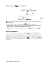
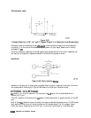
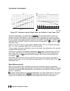
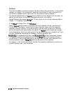
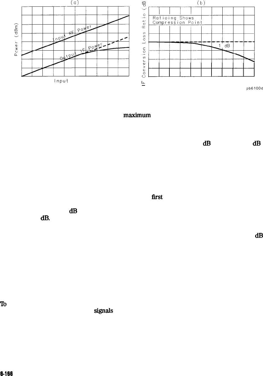
Figure 6-97. Conversion Loss and Output Power as a Function
of
Input Power Level
Conversion compression is a measure of the
maximm
RF input signal level for which the
mixer will provide linear operation. The conversion loss is the ratio of the IF output level to
the RF input level, and this value remains constant over a specified input power range. When
the input power level exceeds a certain maximum, the constant ratio between IF and RF power
levels will begin to change. The point at which the ratio has decreased 1
dB
is called the 1
dB
compression point.
Notice in Figure 6-97 that the output power increases linearly with the increasing input signal
level, until mixer compression begins and the mixer saturates.
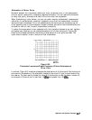
You can measure conversion compression using the same basic test configurations that are used
to measure the conversion loss
‘Ib set up for a conversion compression measurement,
first
measure the conversion loss of the
mixer under test. Set up for a CW measurement at the frequency of interest. Sweeping the
RF drive level over a 25
dB
span soon shows the power level at which the conversion loss
increases by 1
dB.
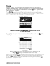
With power meter calibration controlling the RF drive level, and the receiver calibrated to
measure output power, you can make accurate measurements of the output power at the 1
dB
compression point.
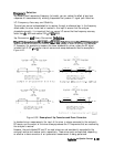
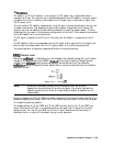
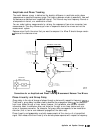
Phase Measurements
When you are making linear measurements, provide a reference for determining phase by
splitting the RF source power and send part of the signal into the reference channel. (This does
not work for frequency offset measurements, since the source and receiver are functioning at
different frequencies.)
lb
provide a reference signal for the phase measurement, you need a second mixer. This mixer
is driven by the same RF and LO
sign&
that are used to drive the mixer under test. The IF
output from the reference mixer is applied to the reference (R) channel of the analyzer.
6-166
Application and Operation Concepts