


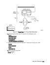
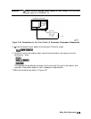
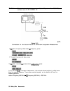
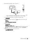
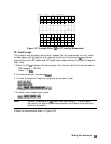
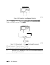

The measurements setup diagram is shown in Figure 3-22.
NETWORK ANALYZER
CW. 200 MHz
CW: BOO MHz
600 MHz
13
dBm
FREO OFFS
ON off
LO
MENU
DOWN
CONVERTER
UP
CONVERTER
RF
>
LO
I
RF < LO
VIEW
MEASURE
RETURN
pg636e
Figure 3-22. Measurement Setup Diagram Shown on Analyzer Display
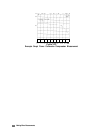
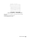
11. To view the mixer’s output power as a function of its input power, press:
..*i/i
i
_
_
;_
;;..,
;_.;
.;.<.
I--
_.
;._
.~
~~~~~
. . . .
. . . . . .
. . .
. .
I
,........
../:
::..
.s.......
..~L~.......~
ii
As..%.>.:;:;
ii
. . . . .
.A..
.>;z
. .
..A
. .
..i............
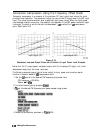
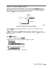
12.
‘lb
set up an active marker to search for the 1
dB
compression point of the mixer, press:
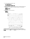
13. Press:
The measurement results show the mixer’s 1
dB
compression point. By changing the target
value, you can easily locate other compression points (for example, 0.5
dB,
3
dB).
See
Figure 3-22.
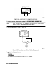
14. Read the compressed power on by turning marker A off.
.:::::,:::::::::::::::::~,:::,:::,.::~
.::p,,:..:j
:s
,,,,,::
m.:
y<<<<<<<::<...
. . .
..z...
_I..
B
~~~~~~
~~~~~~~~~,~~:.
.,...........,,
.,.,.,,
.:::.,
,.::
/;
,...
.._.........._............. :L.;;.:
..:.
.:: :::. . . . . . . . .
.
. . . . . . . . .:
::.
::.~;::..i~~ . . . . . . . . . .
/./..:;>;..
Making Mixer Measurements
3-31