


Setting the Electrical
Delay
This feature adds phase delay to a variation in phase versus frequency, therefore it is only
applicable for
ratioed
inputs.
2. Press
(jjFctn)
and turn the front panel knob, or enter a value from the front panel
keypad to position the marker at a point of interest.
_
. . . .
3.
Press
~~~~~~~~
to automatically add or subtract enough line length to the receiver
A:.,.:.,.,.;;;
..,.,......,,
‘..::.~~~~:.:.~.:..:::~:::..:..:::....:..~.:.:~~:~:..:.:~.
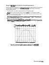
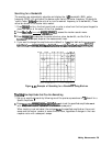
input to compensate for the phase slope at the active marker position. This effectively
flattens the phase trace around the active marker. You can use this to measure the electrical
length or deviation from linear phase.
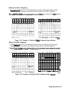
Additional electrical delay adjustments are required on devices without constant group delay
over the measured frequency span.
1
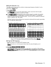
Figure 2-23. Example of Setting the Electrical Delay Using a
Marker
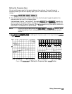
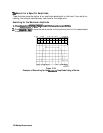
Setting the CW Frequency
1.
‘lb
place a marker at the desired CW frequency, press:
B
and either turn the front panel knob or enter the value, followed by a unit
terminator.
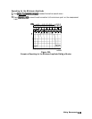
You can use this function to set the marker to a gain peak in an amplifier. After pressing
:~~~~~~~
a&ivate
a
CW
frequency
power
sweep
to
loOk
at
the
g.&.,
compres~on
dtl,
i
;:.;::::..::
. . . . . . . . . . ..
%m
. . . . . . .
i::.i;;u;;;
. . . . . . . . ..
. . . . .
. .
.
li
. . . . .
. . . . .
.A..
...A
’
increasing input power.
Making Measurements 23 1