


MEASUREMENT ERRQRS
Unknown
L
pg659d
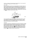
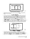
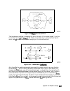
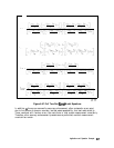
Figure 6-42. Bhjor Sources of Error
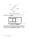
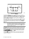
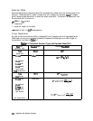
The transmission coefficient is measured by taking the ratio of the incident signal (I) and the
transmitted signal
(‘I)
(see
F’igure
6-43). Ideally, (I) consists only of power delivered by the
source, and
(T)
consists only of power emerging at the test device output.
(1)
)
CT)
*
Forward
S2,M
‘ZIA’
ETF
(+
!T)
+
(I)
Reverse
S,2M
?2M
0-1
S12A
=
E
TR
‘12A
ETR
pg660d
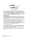
Figure 6-43. Transmission
Coetllcient
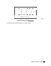
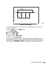
As in the reflection model, source match can cause the incident signal to vary as a function
of test device
&A.
Also, since the test setup transmission return port is never exactly the
characteristic impedance, some of the transmitted signal is reflected from the test set port 2,
and from other mismatches between the test device output and the receiver input, to return
to the test device. A portion of this signal may be re-reflected at port 2, thus affecting
&M,
or part may be transmitted through the device in the reverse direction to appear at port 1,
thus affecting
Sll~.
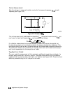
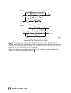
This error term, which causes the magnitude and phase of the transmitted
signal to vary as a function of $ZA, is called load match,
ELF
(see Figure 6-44).
Application and Operation Concepts
6-67