


SYNTHESIZED
SIGNAL GENERATOR
6
dB
ATTENUATOR
I
MIXER
pg61
13d
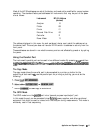
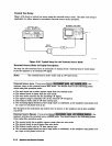
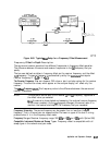
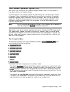
Figure 6-60. Typical
‘l&t
Setup for a Frequency Offset Measurement
Frequency Offset In-Depth Description
The source and receiver operate at two different frequencies in frequency offset operation.
The difference between the source and receiver frequencies is the
Lo
frequency that you
specify.
The two user-defined variables in frequency offset are the receiver frequency, and the offset
(LC)
frequency. The source frequency is automatically set by the
instment
and equals
receiver frequency IF +
Lo
or IF
-
Lo.
The Receiver Frequency. You
can choose a CW value or start and stop values for the receiver
frequency. The stimulus values, which appear on the analyzer display, will affect only the
receiver.
The
ORset Frequency
(L0).
This frequency value is the difference between the source and
receiver frequencies.
Note
The analyzer’s source locks to the receiver
f
the
Lo
frequency, regardless of
the offset value you selected.
Once
the source is phase-locked and sweeping, the analyzer’s source frequency
is not known precisely. As the
Lo
frequency changes, the source tracks it to
maintain the receiver start/stop or CW frequency that you requested.
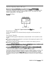
Frequency Hierarchy.
The source frequency can be greater than or less than the
Lo
frequency. That is, the analyzer can measure either the lower or upper of the two IF mixing
products when it is in the frequency offset mode.
Frequency
Ranges. Receiver frequency range: 300
kHz
to 3
GHz
(or 6
GHz
with Option 006)
Compatible Instrument Modes and Sweep
Types. Frequency offset is compatible with all
sweep types in the network analyzer mode.
Application and Operation Concepts
6-121