


Gating
Gating provides the flexibility of selectively removing time domain responses. The remaining
time domain responses can then be transformed back to the frequency domain. For reflection
(or fault location) measurements, use this feature to remove the effects of unwanted
discontinuities in the time domain. You can then view the frequency response of the remaining
discontinuities. In a transmission measurement, you can remove the effects of multiple
transmission paths.
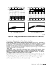
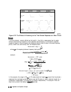
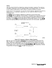
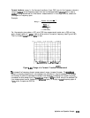
Figure
6-75a
shows the frequency response of an electrical airline and termination.
Figure
6-75b
shows the response in the time domain. The discontinuity on the left is due to the
input connector. The discontinuity on the right is due to the termination.
We
want to remove
the effect of the connector so that we can see the frequency response of just the airline and
termination. Figure
6-75~
shows the gate applied to the connector discontinuity. Figure
6-75d
shows the frequency response of the airline and termination, with the connector “gated out.”
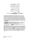
GATING OPERATION
Frequency
Domo
i
n
I___-
+t
pb666d
Figure 6-75. Sequence of Steps in Gating Operation
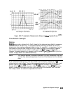
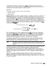
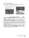
Setting
the gate.
Think of a gate as a
bandpass
filter in the time domain (see Figure 6-76).
When the gate is on, responses outside the gate are mathematically removed from the time
domain trace. Enter the gate position as a start and stop time (not frequency) or as a center
and span time. The start and stop times are the
bandpass
filter
-6
dB
cutoff times. Gates can
have a negative span, in which case the responses inside the gate are mathematically removed.
The gate’s start and stop flags
dellne
the region where gating is on.
Application and
OperationConcepts
6-141