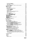
Compatible Sweep Types
........................
External Source Requirements
.....................
Capture Range.
............................
Locking onto a
signal
with a frequency modulation component
......
Tuned
Receiver Mode
...........................
Frequency Offset Menu
..........................
Primary Applications
...........................
Typical Test Setup
............................
Frequency Offset In-Depth Description
..................
The Receiver
Frequency
........................
The Offset Frequency (LO)
.......................
Frequency Hierarchy
..........................
Frequency Ranges
...........................
Compatible Instrument Modes and Sweep Types
.............
Receiver and Source Requirements
...................
Display Annotations
..........................
Error Message
.............................
Spurious
SiiaI
Passband
Frequencies
..................
Harmonic Operation (Option 002
only)
...................
Typical Test Setup
............................
Single-Channel
Operation
.........................
Dual-Channel Operation
.........................
Coupling
Power Between Channels 1 and 2
................
Frequency
Range
............................
Accuracy and input power
........................
Time Domain Operation (Option 010)
.....................
The Transform Menu.
...........................
General Theory
..............................
Time Domain
Bandpass
..........................
Adjusting the Relative Velocity Factor
...................
Reflection Measurements Using
Bandpass
Mode
..............
Interpreting the
bandpass
reflection response horizontal axis
.......
Interpreting the
bandpass
reflection response vertical axis
........
Transmission Measurements Using Bandpass Mode
.............
Interpreting the
bandpass
transmission response horizontal axis
.....
Interpreting the
bandpass
transmission response vertical axis
.......
Timedomainlowpass
...........................
Setting frequency range for time domain low pass
.............
Minimum
allowable
stop frequencies
..................
Reflection Measurements In Time Domain Low Pass
............
Interpreting the low pass response horizontal axis
............
Interpreting the low pass response vertical axis
.............
Fault
Location Measurements Using Low Pass
...............
Transmission Measurements In Time Domain Low Pass
...........
Measuring
smaII
signal
transient response using low pass step
......
Interpreting the low pass step transmission response horizontal axis
...
Interpreting the low pass step transmission response vertical axis
.....
Measuring separate transmission paths through the test device using low
pass impulse mode
.........................
Time Domain Concepts
...........................
Masking
.................................
Windowing
...............................
Range
..................................
Resolution
................................
Response resolution
..........................
6-119
6-119
6-119
6-119
6-119
6-120
6-120
6-120
6-121
6-121
6-121
6-121
6-121
6-121
6-122
6-122
6-122
6-122
6-123
6-123
6-123
6-123
6-124
6-124
6-124
6-125
6-125
6-126
6-127
6-127
6-127
6-128
6-128
6-129
6-129
6-129
6-130
6-130
6-131
6-131
6-131
6-131
6-131
6-133
6-133
6-134
6-134
6-134
6-135
6-135
6-136
6-138
6-139
6-139
Contents-11


