


Basic Measurement Sequence and Example
Basic Measurement Sequence
There are five basic steps when you are making a measurement.
1. Connect the device under test and any required test equipment.
Caution
Damage may result to the device under test if it is sensitive to the analyzer’s
default output power level.
To
avoid damaging a sensitive DUT, be sure to set
the output power appropriately before connecting the dut to the analyzer.
2. Choose the measurement parameters.
3. Perform and apply the appropriate error-correction.
4.
Measure the device under test.
5. Output the measurement results.
Basic Measurement Example
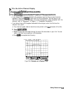
This example procedure shows you how to measure the transmission response of a
bandpass
Glter.
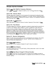
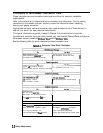
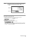
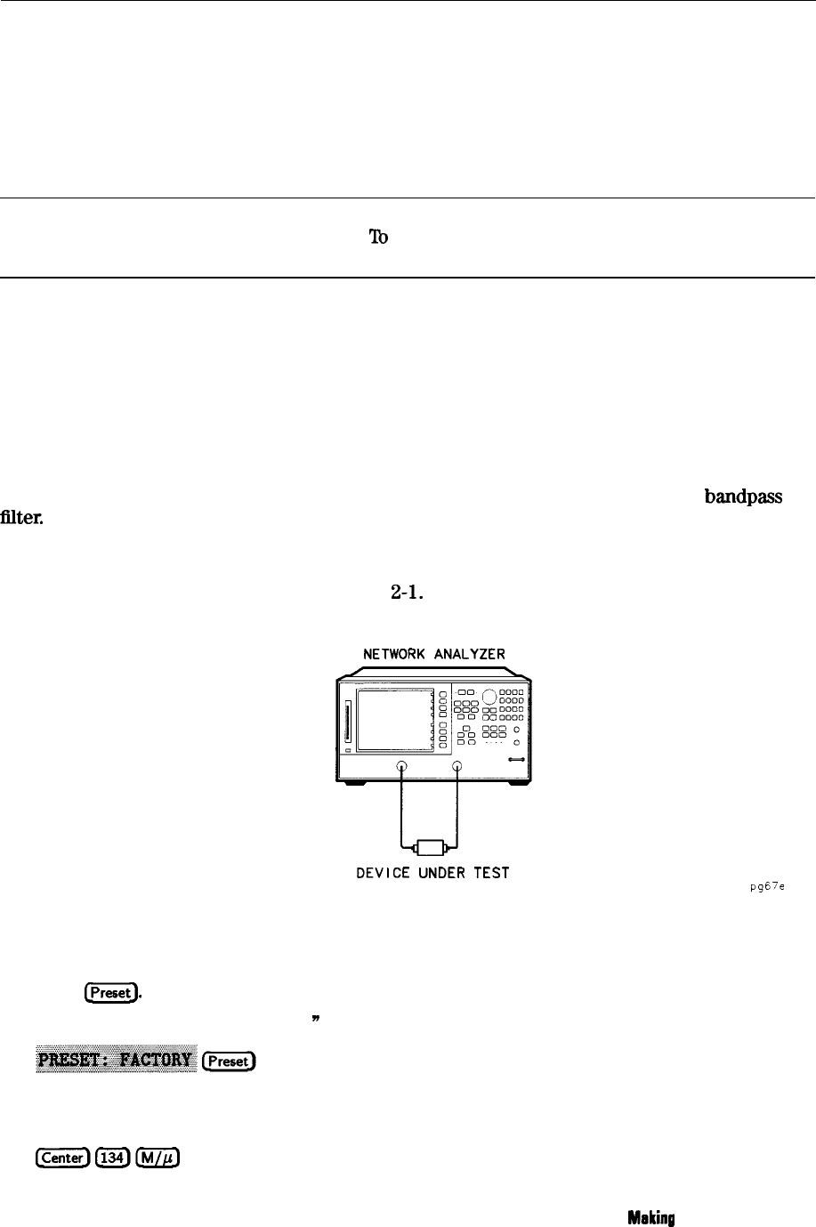
Step 1. Connect the device under test and any required test equipment.
1. Make the connections as shown in Figure
2-l.
NETWORK
ANALYZER
DEVICE
UNDER TEST
pg6’e
Figure 2-1. Basic Measurement Setup
Step 2. Choose the measurement parameters.
2. Press
w.
To set preset to “Factory Preset,
n
press:
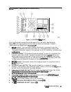
Setting the Frequency Range.
3. To set the center frequency to 134 MHz, press:
[centerl(TzJ(iiiJg
Meking
Measurements 23