


The Calibration Standards
During measurement calibration, the analyzer measures actual, well-defined standards and
mathematically compares the results with ideal “models” of those standards. The differences
are separated into error terms which are later removed during error-correction. Most of the
differences are due to systematic errors-repeatable errors introduced by the analyzer, test set,
and cables-which are correctable.
The standard devices required for system calibration are available in compatible calibration
kits with different connector types Each kit contains at least one short circuit, one open
circuit, and an impedance-matched load. In kits that require adapters for interface to
the test set ports, the adapters are phase-matched for calibration prior to measurement of
noninsertable and non-reversible devices. Other standard devices can be used by specifying
their characteristics in a user-defined kit, as described later in this section under “Modifying
Calibration Kits
n
The accuracy improvement of the correction is limited by the
quality
of the standard devices,
and by the connection techniques used. For maximum accuracy, ensure that the connectors are
clean and use a torque wrench for
final
connections.
Frequency Response of Calibration Standards
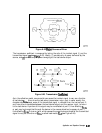
In order for the response of a reference standard to show as a dot on the smith chart display
format, it must have no phase shift with respect to frequency. Standards that exhibit such
“perfect” response are the following:
n
7-mm
short (with no offset)
n
type-N
male
short (with no offset)
There are two reasons why other types of reference standards show phase shift after
calibration:
w
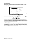
The reference plane of the standard is
electrically
offset from the mating plane of the test
port. Such devices exhibit the properties of a
smaIl
length of transmission line, including a
certain amount of phase shift.
n
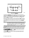
The standard is an open termination, which by
deiinition
exhibits a certain amount of fringe
capacitance (and therefore phase shift). Open terminations which are offset from the mating
plane
will
exhibit a phase shift due to the offset in addition to the phase shift caused by the
fringe capacitance.
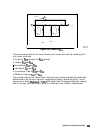
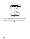
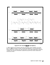
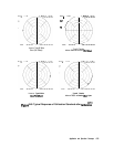
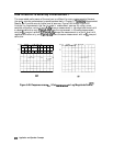
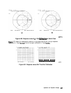
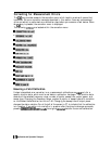
The most important point to remember is that these properties will not affect your
measurements. The analyzer compensates for them during measurement. As a result, if these
standards are measured after a calibration, they will not appear to be “perfect” shorts or
opens, This is an indication that pour unal~z~
ti
working
-Zg
and that it has successfully
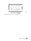
performed a calibration. Figure 6-48 shows sample displays of various calibration standards
after calibration.
Application and Operation Concepts
6-73