


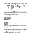

15
Jun
1994
15:05:13
CHl
S,,
delay
10
ns,
REF
0
s
‘-
J
16
\
I
STFlRT
75.000
000
MHz
STOP
175
000
000
MHz
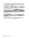
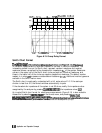
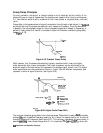
Figure 6-13. Group Delay Format
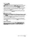
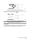
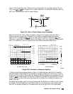
Smith Chart Format
I:
:..:
. . . .
.:<<::<r
i
:
”
,,::
::,:,
:.:.:.:.:.:
_
:.:.:.:.:.:.:.:....
me
;~~,~~~~T
softkey
&plays
a
Smith
&a&
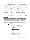
fom-&(see
Figure
6-14).
This
is
used
in reflection measurements to provide a readout of the data in terms of impedance. The
intersecting dotted lines on the Smith chart represent constant resistance and constant
reactance values, normalized to the characteristic impedance,
ZO,
of the system. Reactance
values in the upper half of the Smith chart circle are positive (inductive) reactance, and
those in the lower half of the circle are negative (capacitive) reactance. The default marker
readout is in ohms
(Q)
to measure resistance and reactance
(R+jX).
Additional marker types are
available in the Smith marker menu.
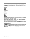
The Smith chart is most easily understood with a full scale value of 1.0. If the scale per
division is less than 0.2, the format switches automatically to polar
If the characteristic impedance of the system is not 50 ohms, modify the impedance value
_
;.
..,.,.,.
~
)
_
,,,
recognized by the analyzer by pressing
(ETJ
~J!##l&
~~~~~
(the impedance value)
@.
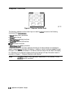
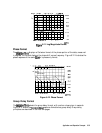
An inverted Smith chart format for admittance measurements (Figure 6-14) is also available.
.,..,...
;
i
.._.
.,.,..
,.,..,.,,.,.;
_._/
._
;.
..,.,.,.,.
.
Access this by selecting
~~~~~~~~
m the format menu, and pressing
CMarker)
. . . . . . . . . . . . . . . . . . . . .
.
.:::::
. . . . . . . . . . . . . . . . .
_
,.:.:...:.:.
/.
:
i:.
.)
.<:.
:.~.:.:.:.~~.:;~...:.:
.:.:.:.:.:~.:~~.:.:.:.:.:.:.:.:.:.:.:.:.:.~:.:.:.:.:~.:.:.:..:
,.;:
~~~~~~~
~~~~~~~~
~~~~:~~~~.
me
Smith
&a
is
inverted
ad
maker
values
:.
./
.:::::::../
,,.
i::;T::::;:..*
.:::..
;;:;;<;..;.;,;
,,
,..._.........................,..~...................~.......~.......~.~, ;;,.~~/
. . . . . . . .
. .
;;...;;;:;;.;;>;:;;;
.
.
. . . . . . . . . . . . . .
.:;::.i;.i
. . .
. .
:,.,.:,
~..,.,...,.i
::.
.::
,.,..
. . . .
. .
:..
.:,.::....
.
. .
. . . . .
. . . .
::::...
,.;.::..
:,.,..
.::
.._..
.:.
,::
are read out in siemens (S) to measure conductance and susceptance (G+jB).
6.34
Application and Operation Concepts