


Deleting Frequency Segments
:)
:
..;.,
.,:,.,
~
.:
,..,....
i
,:x~,:
MY=?
y
,.<$W2.Y?<
.z.,:y;;;;;.:’
.i
I-
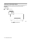
Access the “Segment Modify Menu” by pressing
@
:Pm
.&l&i
~~~?~~~~~~~~~~~,
.::.
.,.
:..:.:.:
;,.,....,.
:.:.::.:
.,.,.,.
:.:.:..“‘:..
::.::...i
,,.
,.
,..,.,.,.,.,.;
a........../
.
..si.ii
/.
. . . .
..%A
,.
,,....
.:
,............._...................::...::...
:..;;.:;
..,,.....,.,,
,.., ,,,
I,~~~~~~~~~~~~~~~~:~~
(or
~~~~~~~~~~~-~~~~~
B.;
depending
on
where
the
segment
is
.;.::i/
P:~<::..:::..;.;.;
./,..,,,,,
.A?.
,
that you want to delete).
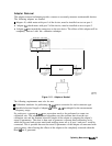
2.
Identify the segment that you want to delete by pressing
&&##$%!
and using the
@)
and
@)
keys to locate and position the segment next to the pointer
(>),
shown on the display. Or
press
~~~~~~~:
and enter the segment number followed by (XJ
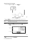
3.
press
‘D&j&
..:
i;..:..
-
The analyzer deletes the segment and moves the remainder of the segments up one number.
4.
You could also delete all the segments in a list by pressing
~~,:~~~~~~
~~.
5-
Press
@I#
when you are Wished modifying the segment list.
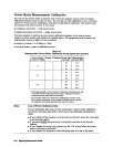
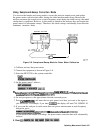
Compensating for Directional Coupler Response
If you use a directional coupler to sample power in your measurement conhguration, you
should enter the coupled arm power loss value into the power loss table, using the following
procedure. You can enter the loss information in a single segment, and the analyzer will assume
that the value applies to the entire frequency range of the instrument. Or, you can input actual
measured power loss values at several frequencies using up to 55 segments, enhancing power
accuracy.
The
analyzer
shows the notation
EMPTY,
if you have not entered any segment information.
:::::::.
*
;.....
,,..,.
. . .
.;
.~~;
,”
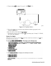
2.
To create the
first
segment, press
@$~
#&#V@K!J~
and enter a frequency of a correction
factor data point, followed by the appropriate key:
@J
Irln_u
Lk/m.
.
.
.
.
.
.
ii
.
.
.
.
.
.
.
<..
I
I..
.
3.
Press
~&I~~
and enter the power loss that corresponds to the attenuation of the directional
.........
i ..<a:
.
. . .
.
coupler (or power splitter) at the frequency that you have entered in the previous step.
Complete the power loss entry by pressing
(XJ
@@.
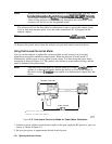
Note
Remember to subtract the through arm loss from the coupler arm loss before
entering it into the power loss table, to ensure the correct power at the output
of the coupler.
4. Repeat the previous two steps to enter up to 55 frequency segments, depending on the
required accuracy.
You may enter multiple segments in any order because the analyzer automaticalIy sorts them
and lists them on the display in increasing order of frequency.
If you only enter one frequency segment, the analyzer assumes that the single value is
valid
over the entire frequency range of the correction.
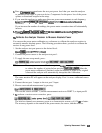
5.
After you have entered all the segments, press
~&J&$:
-?...
. . . . . . . . . . . . . . . .
..i..
6.
Press
Lcall
................
..............
.:..:
.........................................................
~~~~~~~~~,~~~
to
activate
the
power
loss
compensations
...........................
-.
....................
.
............
................
5-36 Optimizing Measurement
Results