


Smoothing
Smoothing (similar to video
filtering)
averages the formatted active channel data over a portion
of the displayed trace. Smoothing computes each displayed data point based on one sweep
only, using a moving average of several adjacent data points for the current sweep. The
smoothing aperture is a percent of the swept stimulus span, up to a maximum of 20%.
Rather than lowering the noise floor, smoothing
ilnds
the mid-value of the data. Use it
to reduce relatively small peak-to-peak noise values on broadband measured data. Use a
sufficiently high number of display points to avoid misleading results. Do not use smoothing for
measurements of high resonance devices or other devices with wide trace variations, as it will
introduce errors into the measurement.
Smoothing is used with Cartesian and polar display formats. It is also the primary way to
control the group delay aperture, given a
fixed
frequency span. (Refer to “Group Delay
Principles” earlier in this section.) In polar display format, large phase shifts over the
smoothing aperture will cause shifts in amplitude, since a vector average is being computed.
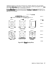
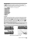
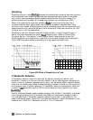
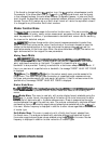
Figure 6-26 illustrates the effect of smoothing on a log magnitude format trace.
pga170-c
Figure 6-26. Effect of Smoothing on a Trace
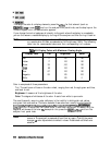
IF Bandwidth Reduction
IF bandwidth reduction lowers the noise floor by digitally reducing the receiver input
bandwidth. It works in all ratio and non-ratio modes. It has an advantage over averaging as it
reliably filters out unwanted responses such as spurs, odd harmonics, higher frequency spectral
noise, and line-related noise. Sweep-to-sweep averaging, however, is better at filtering out very
low frequency noise. A tenfold reduction in IF bandwidth lowers the measurement noise floor
by about 10
dl3.
Bandwidths less than 300 Hz provide better harmonic rejection than higher
bandwidths
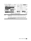
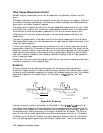
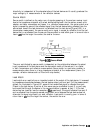
Another difference between sweep-to-sweep averaging and variable IF bandwidth is
the
sweep
time. Averaging displays the first complete trace faster but takes several sweeps to reach a
fully averaged trace. IF bandwidth reduction lowers the noise floor in one sweep, but the
sweep time may be slower. Figure 6-27 illustrates the difference in noise floor between a trace
measured with a 3000 Hz IF bandwidth and with a 10 Hz IF bandwidth.
642
Application and Operation Concepts