


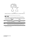
One-Port Reflection Error-Correction
H
removes directivity errors of the test setup
n removes source match errors of the test setup
w
removes frequency response of the test setup
You can perform a l-port correction for either an
S11
or an
S22
measurement. The only
difference between the two procedures is the measurement parameter that you select.
Note
This is the recommended error-correction process for all reflection
measurements, when full two-port correction is not used.
1. Press
w).
2. Select the type of measurement you want to make.
q If you want to make a reflection measurement on PORT 1 (in the forward direction,
&),
leave the instrument default setting.
q If you want to make a reflection measurement on PORT 2 (in the reverse direction, S&,
press:
;
,,,,
;;,>
;+:;:
;.:;$y,;:<>z%z
. .
...::..:.
:.
I~.~.~.~.~~.~.~.~.~.~.
..J....
m
~~~~:~~~~~~~~~~~
/.>::........
. . . . . . .
. .
..~.~.~..~.~.~.~.~..~
L
. . . . .../
.::
.A..
>..;
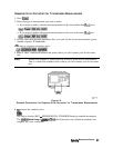
3. Set any other measurement parameters that you want for the device measurement: power,
number of points, IF bandwidth.
4. To access the measurement correction menus, press:
Ical]
..,.,.,
.,.
,,.,.,............P
..:....:
/,.,.,.,
:,.~::::::::::..::::.:.:.:.:.:.:.:.:
5.
If
you
dbrationkit
is
different
thm
the
kit
specified
m&r
the
~~~~~~~~~~
softkey,
:::
.._
.:::;..:::
.A....
.
.
..z..
.A..
.
.
.
.
.
.
..
.
.
.
.
.
.
.
.
.
.
.
.
.
.
.
.
.:
/n>..>:.i
press:
3.;
.<;“;
:g
~~~~~:
~~,~~~~~~’
(sele&
you
type
of
kit)
~~
........
. . .
...
:.,....<~<<f.:....
;;;:m<<<.
:
. . . . . . . . . . .
.w;;;
. . . . . . . . . . . . . . . . . . . . . . . . .
;;;;,.,.,s
. . . . .
i,::;._.sA.>
.
_...>-5.
If your type of calibration kit is not listed in the displayed menu, refer to the “Modifying
Calibration Kit Standards” procedure, located later in this chapter.
&
~
sele~ the co*ection
type,
press
~~~~~~~~~~:~~~
and
seled
the
co*ection
type.
:.<.:.:.;
. . .
. . .
.~.~:....~~~.:~~~~........;
. . . . . . . . . . .
:.......!.:
,....
.._:.::
.
...
. . .
.
.
i...~~..~....~.~
.
..>
..i..
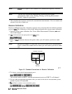
q If you want to make a reflection measurement at PORT 1, press:
:~~~~~~~~;
:
1.....................................~
::.._
;:.<~~i.:E.:.:
.._.....
q If you want to make a reflection measurement at PORT 2, press:
~~~~~~~~:
../.;Liii.~~...:
. . . . . . . . . . . . . . . . . . . . . . . .
.%%
. . . . . . . .
..v
>;u:..
.A....
.%v;..;>;;A.
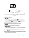
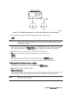
7. Connect a shielded open circuit to PORT 1 (or PORT 2 for an
SZZ
measurement).
Note
Include any adapters that you will have in the device measurement. That is,
connect the calibration standard to the particular connector where you will
connect your device under test.
6.18
Optimizing Measurement Results