


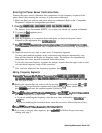
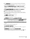
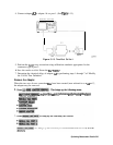
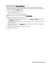

4. Connect adapter
A3
to adapter Al on port 1. (See
F’igure
5-13.)
NETWORK ANALYZER
REFERENCE
PORT 2
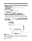
Figure 5-13. Two-Port Cd
Set 2
5. Perform the
2-port
error correction using calibration standards appropriate for the
connector type at port 2.
6. Save the results to disk. Name the
fSle
“PORTB.”
7. Determine the electrical delay of adapter
A3
by performing steps 1 through 7 of “Modify
the Cal Kit Thru Definition.”
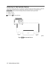
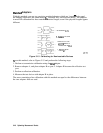
Remove the Adapter
When the two sets of error correction
fles
have been created (now referred to as
“cal
sets”),
the adapter may be removed.
,
~~~~~.~~~~~~(This
provides
a
quick
reference
guide
to
using
*e
adapter
.,.,.,.,.;
_.,.,.,.,.,.,.,....,..................,
_
;;
.,......
,...//
..-........
-
removal technique.)
~,~,...,~.~.~,~,~,~,~,~.~,~.~,~,~,~,.,~,~,.,.;
:.:.;.:.
;;,>
,,~,~,.,~,,,~
<.:.:,
:~:;.:,.:::,,~.“:~~~~~
,:~~~~..~~~~~~~~~~~~:~~~~~~:..
.
~~~~~~~:
,,.,,,
,,
..,
.,.,..,.,.,;.;:.:...
,,,,
.;;..:.:.:.:.
:.
::.:.:::
/
n
~~~~~~~~~
i
. . . . . . . . .
s.2;
. . . . . . . . . . . . .
/
. . . . . . .
.
.::::..::
.
.
. . . . . . .
.i
.:..
Optimizing Measurement Results 543