


8.To
access the gate function menu, press:
9.
10.
11.
To set the gate parameters, by entering the marker value, press:
(?XJ
(%iJJ,
or turn the front panel knob to position the
“T”
center gate marker.
‘RI
set the gate span, press:
::.i
%pM+
(1.2)
m
or turn the front panel knob to position the “flag” gate markers.
RI
activate the gating function to remove any unwanted responses, press:
##&$
‘jg.g
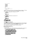
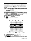
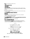
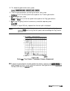
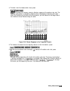
As shown in Figure 2-60, only response from the main path is displayed.
Note
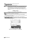
You may remove the displayed response from inside the gate markers by
pressing
;Sga:’
and turning the front panel knob to exchange the “flag” marker
,....__.....
i
ii. //..>..
positions
Gating
Figure 2-60.
aw000023
in
a Time Domain Transmission Example Measurement
12.
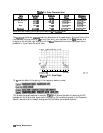
To adjust the gate shape for the best possible time domain response, press
~~~~~~
and
.._...............
-
select between minimum, normal, wide, and maximum. Each gate has a different
passband
flatness, cutoff rate, and
sidelobe
levels.
Mating Measurements
2-86