


:..: .. .A.
..‘.
,i.;;:.
..,,
:p..<<,:p
G(”
..,,
cc,,
.
~~~~~~~~~~~~
dehes
the
standard
type
to
be
a
load,
but
with
a
arbitrary
i
:;;.:..:;;;..~;...:.;......~~~.~~.~~~.........;;;~~:::.;;;~;~;..:~
.
.
...
:..:::hii;
..
.
.
.A..
.>;.i
ii
.r>
..A..
>::
.A..
.i
.
.
.
.
.
i/i
impedance (different from system ZO).
~~~~~~~~~~~~
&-~wsyou
to
specifythe(arbitrary)impedance
ofthe
st~d~d,~
i......:,........,.
:...
i:....: ..T
:,7;....
..,..
. . . . ..i.......,
,..i
. .
..c.
. . . . . . .
.i
.
..A.
. . . . .
ii
i
. . . . . . .. . . . . . .
ohms.
:,..:."
i:,,;
,.
‘KC$&@
defines the load as a
fixed
(not sliding) load.
,~.~,....:.:.:~:~::
::,,
:::::::::.:
..A<.
i
. . . . . . . .
.i.
. . . .
,.
_
.
$%jJ,lQXG’
defmes
the load as a sliding load. When such a load is measured during
.....................
.::.:
::.i
calibration, the analyzer will prompt for several load positions, and calculate the ideal load
value from it.
Normally,
arbitrary impedance standards are
fixed
rather than sliding.
Any standard type can be further
dehned
with offsets in delay, loss, and standard impedance;
assigned
minimum or maximum frequencies over which the standard applies, and defined as
.i.
. . . . . . . .
.:
. . . . ..:::, ..“...,;,.,.“,““,““;.,.,.,..“~,.,~,... ..,
;.,
..,,.,.,.,./
co~orwaveguide.
l"he
~~~~~~~~F~~
softkey
provides
access&
the
specify
off&menu
(described next).
.,.,.,.,.,.,.,.,.,.,.,.,.
*
The
~~~~~
softkey allows you to
deiine
a distinct label for each standard, so that
.
:;..
..i
.
::
.
._..
_.....
the analyzer can prompt the user with explicit standard labels during calibration (such as
SHORT). The function is similar to
delining a display title, except that the label is limited to ten
characters.
:
. . . .
/,.,.
./
.,.$g@:.:~.:<~~
..:
:..z:z:.:.:~:T...
. . :
.
...”
;
..,.,.,.,.,.,.,.,.,..._._i
//...,_
After each standard is deiined, including offsets, the
~~~~~~~~~;“~~~.~~
softkey
will
terminate the standard deilnition.
Specify Offset Menu
The specify offset menu allows additional specifications for a
user-dellned
standard. Features
specitled
in this menu are common to all five types of standards.
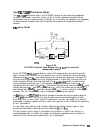
Offsets may be specified with any standard type. This means
defining
a uniform length of
transmission line to exist between the standard being
deilned
and the actual measurement
plane. (Example: a waveguide short circuit terminator, offset by a short length of waveguide.)
For reflection standards, the offset is assumed to be between the measurement plane and the
terminating element of the standard (one-way only). For transmission standards, the offset is
assumed to exist between the two reference planes (in effect, the offset is the thru). For both
reflection and transmission, the offset is entered as a one-way offset. Three characteristics of
the offset can be
defined: its delay (length), loss, and impedance.
In addition, the frequency range over which a particular standard is valid can be deiined with
a
minhmun
and maximum frequency. This is particularly important for a waveguide standard,
since the
minimum frequency is used to
deilne
the waveguide cutoff frequency. Note
that
several band-limited standards can together be
defmed
as the same “class” (see specify class
menu). Then, if a measurement calibration is performed over a frequency range exceeding a
single standard, additional standards can be used for each portion of the range.
Lastly, the standard must be deiined as either coaxial or waveguide. If it is waveguide,
dispersion effects are calculated automatically and included in the standard model.
The following is a description of the softkeys located within the specify offset menu:
.
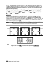
~~~~~~~~~
allows
you
to
specify
the
one-way
electrical
delay
from
the
measurement
;;~;.;~;=:~~~~~~~..~...
. . . . . . .
i.../LI
IT
.::..::
.::.
.:
ii ii . .
..A
. . . . .
.A....
i.
(reference) plane to the standard, in seconds (s). (In a transmission standard, offset delay is
the delay from plane to plane.) Delay can be calculated from the precise physical length of
the offset, the permittivity constant of the medium, and the speed of light.
In coax, group delay is considered constant. In waveguide, however, group delay is
dispersive, that is, it changes significantly as a function of frequency. Hence, for a waveguide
standard, offset delay must be
deilned
as though it were a TEM wave (without dispersion).
Application and Operation Concepts 6-67