


Rear
Panel Features and Connectors
0
19
pg63e
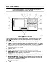
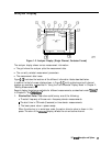
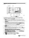
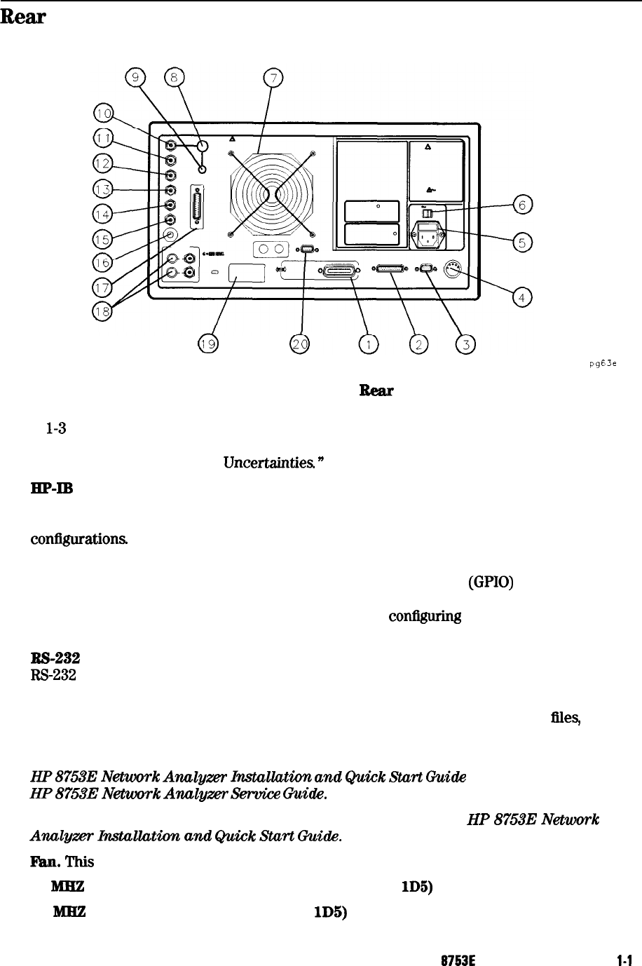
Figure 1-3. HP 8753E Bear Panel
Figure
l-3
illustrates the features and connectors of the rear panel, described below.
Requirements for input signals to the rear panel connectors are provided in Chapter 7,
“Specifications and Measurement
Uncertanuies
n
1.
2.
3.
4.
5.
6.
7.
8.
9.
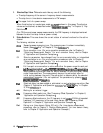
HP-Ill connector. This allows you to connect the analyzer to an external controller,
compatible peripherals, and other instruments for an automated system. Refer to the
“Compatible Peripherals” chapter in this document for HP-IB information, limitations, and
coniigurations
PARALLEL interface.
This connector allows the analyzer to output to a peripheral with
a parallel input. Also included, is a general purpose input/output
(GPIO)
bus that can
control eight output bits and read five input bits through test sequencing. Refer to the
“Compatible Peripherals” chapter for information on
con@uing
a peripheral. Also refer
to “Application and Operation Concepts” for information on GPIO.
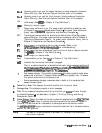
RS-232
interface
This connector allows the analyzer to output to a peripheral with an
W-232 (serial) input.
KEYBOARD input (mini-DIN). This
connector allows you to connect an external
keyboard. This provides a more convenient means to enter a title for storage ties, as well
as substitute for the analyzer’s front panel keyboard.
Power cord receptacle, with fuse.
For information on replacing the fuse, refer to the
HP87533
Network
Anulgzer
Instullution
and
Quick
Start
Guide
or the
HP
87533
Network
Analps-
Seruice
Guide.
Line voltage selector switch.
For more information refer to the
HP
87533
Network
Analyzer
Installation
and
Quick
Start
Guide.
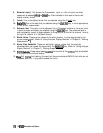
l%.n.
This
fan provides forced-air cooling for the analyzer.
10
ME
PRECISION REFERENCE OUTPUT. (Option lD5)
10
MHZ
REFERENCE ADJUST. (Option
lD5)
HP
8753E
Description and Options
l-1
1