


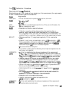

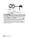
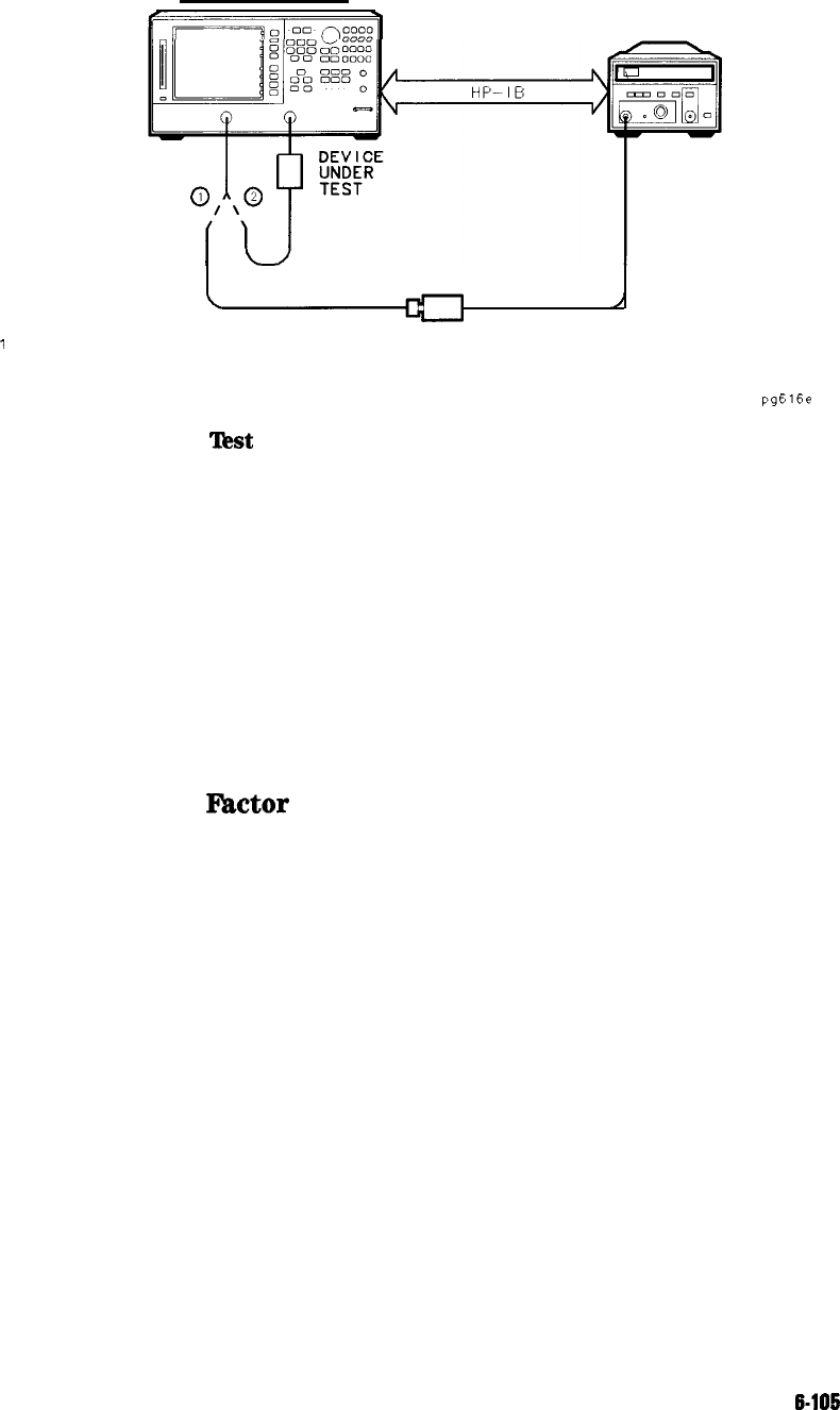
NETWORK ANALYZER
POWER METER
POWER SENSOR
0
1
CONNECT FOR INITIAL SWEEP
0
2 CONNECT FOR SUBSEQUENT SWEEPS
pg616e
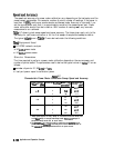
Figure 6-56. ‘I&t Setup for Sample-and-Sweep Mode
Power Loss Correction List
If a directional coupler or power splitter is used to sample the RF power output of the analyzer,
the RF signal going to the power meter may be different than that going to the test device. A
directional coupler will attenuate the RF signal by its specified coupling factor. The difference
in attenuation between the through arm and the coupled arm (coupling factor) must be entered
using the loss/sensor list menu. Non-linearities in either the directional coupler or power
splitter can be corrected in the same way.
Power loss information is entered in much the same way as limit line parameters. Up to 12
segments may be entered, each with a different attenuation value. The entered data will not
be lost if the instrument’s power is cycled.
Power Sensor Calibration
Factor
List
Two power sensor calibration data lists can be created in the analyzer. No single power sensor
covers the entire frequency range of the analyzer, therefore the calibration data for two
different power sensors must be available. The entered data will not be lost if the instrument’s
power is cycled.
Application and Operation Concepts
6-l
06