


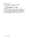
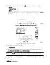
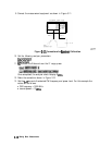
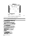

9. Connect the measurement equipment as shown in Figure 3-11.
pg625e
Figure
3-11.
Connections for
Eeceiver
Calibration
10.
11.
12.
13.
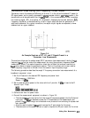
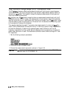
Set the following analyzer parameters:
@jgg=p
To
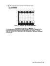
calibrate the B-channel over the IF range, press:
Once completed, the analyzer should display 0
deem.
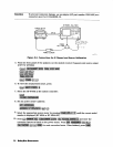
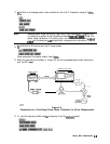
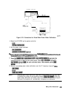
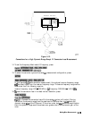
Make the connections shown in Figure 3-12.
Set the
Lo
source to the desired CW frequency and power level. For this example the
values are as follows:
n
CW frequency = 1500 MHz
n
source power = 13
dBm
3-14
Making Mixer Measurements