


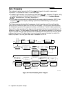
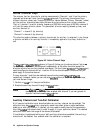

The Built-In ‘I&t Set
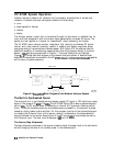
The HP 8753E features a built-in test set that provides connections to the test device, as well
as to the signal-separation devices. The signal separation devices are needed to separate the
incident signal from the transmitted and reflected signals. The incident signal is applied to the
R channel input through a jumper cable on the front panel. Meanwhile, the transmitted and
reflected signals are internally routed from the test port couplers to the inputs of the A and B
sampler/mixers in the receiver. Port 1 is
cOMeC!ted
to the A input and port 2 is connected to
the B input.
The test set contains the hardware required to make simultaneous transmission and reflection
measurements in both the forward and reverse directions. An RF path switch in the test set
allows reverse measurements to be made without changing the connections to the test device.
The Receiver Block
The receiver block contains three sampler/mixers for the R, A, and B inputs The signals
are sampled, and mixed to produce a 4
kHz
IF (intermediate frequency). A multiplexer
sequentially directs each of the three signals to the ADC (analog to digital converter)
where it is converted from an analog to a digital signal. The signals are then measured and
processed for viewing on the display. Both amplitude and phase information are measured
simultaneously, regardless of what is displayed on the analyzer.
The Microprocessor
A microprocessor takes the raw data and performs all the required error correction, trace
math, formatting, scaling, averaging, and marker operations, according to the instructions
from the front panel or over HP-IB. The formatted data is then displayed. The data processing
sequence is described in “Data Processing” later in this chapter.
Required Peripheral Equipment
Measurements require calibration standards for vector accuracy enhancement
(error-
correction), and cables for interconnections. Model numbers and details of compatible power
splitters, calibration kits, and cables are provided in Chapter 11, “Compatible Peripherals
’
Application and Operation Concepts 6-3