


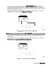
NETWORli
ANALYZER
pg624e
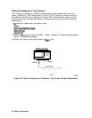
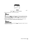
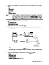
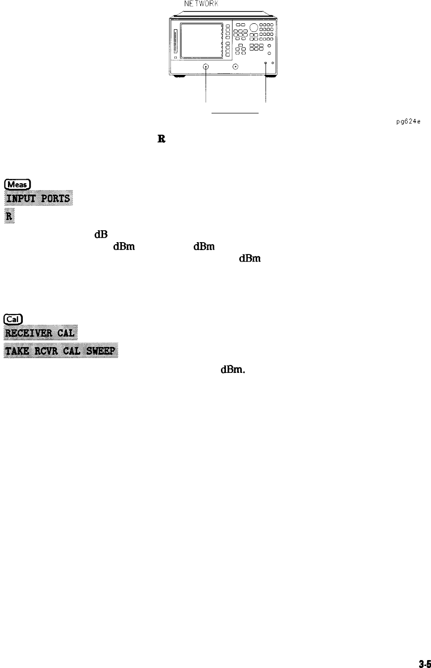
Figure 3-3.
B
Channel
External Connection
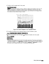
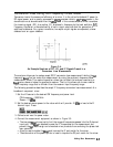
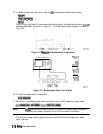
4. Measure the output power in the R channel by pressing:
Observe the 13 to 16
dR
offset in measured power. The actual input power level to the R
channel input must be 0
dBm
or less, -10
dRm
typical, to avoid receiver saturation effects
The minimum signal level must be greater than -35
dBm
to provide sufficient signal for
operation of the phaselock loop.
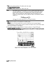
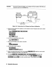
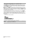
5. You cannot trust R channel power settings without knowing about the offset involved.
Perform a receiver calibration to remove any power offsets by pressing:
Once completed, the R channel should display 0
dRm.
Changing power ranges will require a
recalibration of the R channel.
Mating Mixer Measurements
3-S