


Required Equipment
Characterizing a duplexer requires that the test signals between the analyzer (a 2-port
instrument) and the duplexer (a 3-port device) are routed correctly. This example uses one of
the following adapters to perform this function:
n
HP 8753E Option
K36
duplexer test adapter
n
HP 8753E Option
K39
3-port
test adapter
You must also have a set of calibration standards for performing a full 2-port calibration on
your test set up.
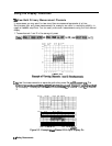
Procedure for Characterizing a Duplexer
1. Connect the test adapter to the analyzer according to the instructions for your particular
model. Connect any test
llxture
or cables to the duplexer test adapter.
2.
Press=.
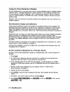
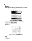
3. Set up the stimulus parameters for channel 1 (center/span frequencies, power level, IF
bandwidth). This example uses a span of 120 MHz centered at 860 MHz.
PressIcenter)@ZJLM/U)CSpan)(EJLM/U)
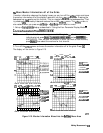
4. Uncouple the primary channels from each other:
.,;
.,....
.,.,..
,,...:...
. . . . . . . . . . . . . . . . . . . . .
.........
Press
m),
set
~~~~~~
to OFF.
(This is necessary in order to set the test set I/O independently for each channel.)
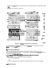
Note
Make sure you connect the standards to the
TX
port of the test adapter (or a
cable attached to it) for the FORWBD calibration and to the Ant port for the
REVERSE calibration. The
LEDs
on the test adapter indicate the active ports:
a brightly lit LED indicates the source port; a dimly lit port indicates the input
port; an unlit LED indicates no connection.
7.
When the calibration has been completed, save the instrument state:
8.
9.
Press
@iLZiJ
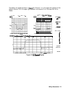
Set up channel 2 for the same stimulus parameters as channel 1.
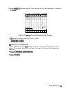
10.
11.
Set up control of the test adapter so that channel 2 is measuring the receive path of the
duplexer: (Uncoupling the channels allows a different calibration for each signal path.)
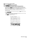
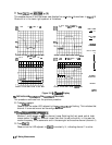
Perform a full
2-port calibration on channel 2:
2.14
Making Measurements