


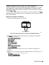
3. Substitute a thru for the device and perform a response calibration by pressing:
&g
~:~~~~~~~~;
~~~~~~~,,
;@Ji@.
4.
Reconnect your test device.
5. To better view the measurement trace, press:
,,..
. .
(7)
:&q#j
:
<&&$
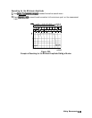
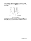
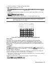
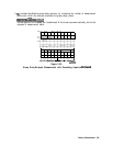
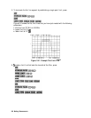
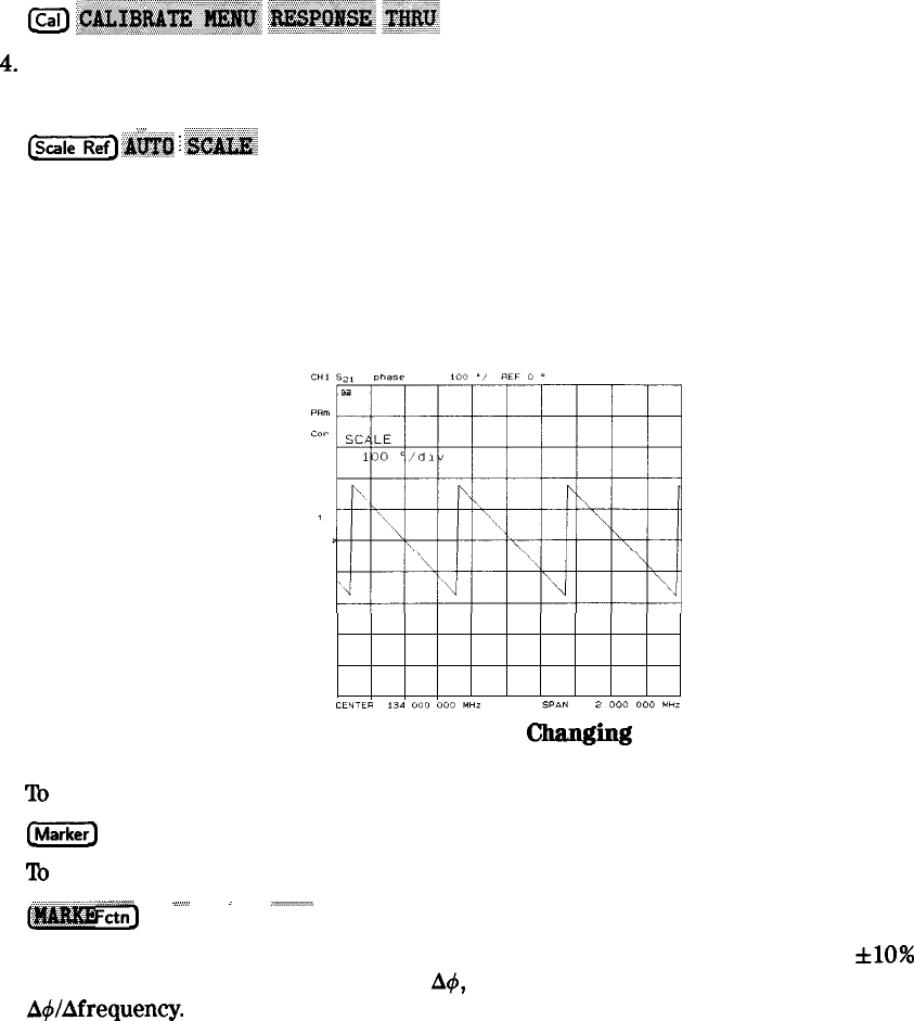
Notice that in Figure 2-34 the SAW filter under test has considerable phase shift within only
a 2 MHz span. Other filters may require a wider frequency span to see the effects of phase
shift.
The linearly changing phase is due to the device’s electrical length. You can measure this
changing phase by adding electrical length (electrical delay) to compensate for it.
Figure 2-34. Linearly
changing
Phase
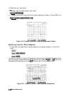
6.
To
place a marker at the center of the band, press:
e
and turn the front panel knob, or enter a value from the front panel keypad.
7.
To
activate the electrical delay function, press:
.MARKER DELAY
(Markeri$$&@,$&;TT
.;>..;;;;
i
..>;;;;;;.;/i/.*
Fa”,
~~~~~~~,
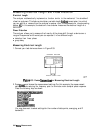
This function calculates and adds in the appropriate electrical delay by taking a &lo%
span about the marker, measuring the
A4,
and computing the delay as the negative of
AdlAfrequency.
Making Measurements 241