


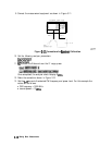

15. To select the converter type and a high-side
Lo
measurement configuration, press:
&&f&g
:
..,.
.,.v.
.;.
:.
~6~,~~.~~~~.
/....~~/...~
. . . .
T.,,
..: ;L?.::<:
. . . . . . . .
,,,,......
&&Jal~
.i
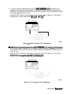
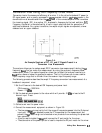
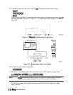
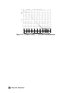
Notice in this high-side LO, down conversion configuration, the analyzer’s source is
actuahy
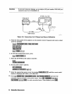
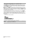
sweeping backwards, as shown in Figure 3-7. The measurement setup diagram is shown in
Figure 3-8.
100
MHz
350
550
650
900
1
GHz
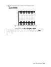
Figure 3-7.
Diagram
of Measurement Frequencies
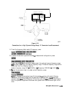
NETWORK ANALYZER
FREO
OFFS
ON
off
LO
MENU
DOWN
CONVERTER
UP
CONVERTER
RF
>
LO
RF
<
LO
VIEW
MEASURE
RETURN
pg6155d
FIXED
LO:
1
GHz
LO
POWER.
13
dBm
pg627e
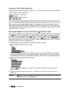
Figure 3-8. Measurement Setup from Display
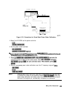
16. To view the measurement trace, press:
17. To perform a one-sweep power meter calibration over the RF frequency range, press:
Note
Do
not
reduce the number of points to perform this power meter calibration.
Reducing the number of points will turn off the receiver calibration.
The analyzer is now displaying the conversion loss of the mixer calibrated with power
meter accuracy.
3-10
Making Mixer Measurements