


Characterizing Microwave Systematic Errors
One-Port Error Model
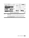
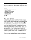
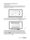
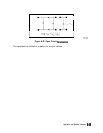
In a measurement of the reflection coefficient (magnitude and phase) of a test device, the
measured data differs from the actual, no matter how carefully the measurement is made.
Directivity, source match, and reflection signal path frequency response (tracking) are the
major sources of error (see Figure 6-32).
Measured
Data
pg649d
Figure 6-32. Sources of Error in a Reflection Measurement
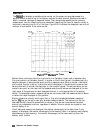
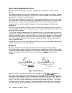
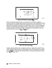
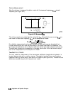
lb characterize the errors, the reflection coefficient is measured by
lirst
separating the incident
signal (I) from the reflected signal (R), then taking the ratio of the two values (see Figure 6-33).
Ideally, (R) consists only of the signal reflected by the test device
(&IA,
for
S11
actual).
s
K
11M
=
f
.I
Unknown
pg650d
Figure 6-33. Reflection
CoefHcient
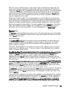
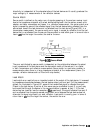
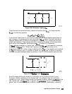
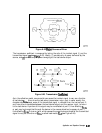
However,
ail
of the incident signal does not always reach the unknown (see Figure 6-34).
Some of (I) may appear at the measurement system input due to leakage through the test
set or through a signal separation device. Also, some of (I) may be reflected by imperfect
adapters between a
signaI
separation device and the measurement plane. The vector sum of
the leakage and the miscellaneous reflections is the effective directivity, Eur. Understandably,
the measurement is distorted when the directivity signal combines vectorally with the actual
reflected signal from the unknown,
&A.
Application end Operation
Conoepts
6-61